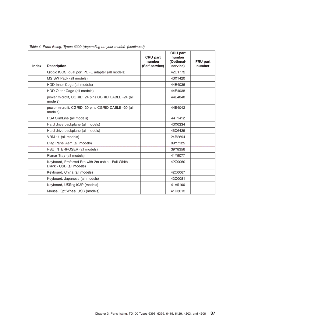
Hardware Maintenance Manual
Page
Hardware Maintenance Manual
Portions Copyright International Business Machines Corporation
Third Edition June Copyright Lenovo
Chapter 2. Configuration information and instructions
Contents
Chapter 4. Removing and replacing server components
iv ThinkServer TD100 and TD100x Hardware Maintenance Manual
Contents
Getting help and technical assistance
Index
vi ThinkServer TD100 and TD100x Hardware Maintenance Manual
Safety
Inspecting for unsafe conditions
Guidelines for trained service technicians
Guidelines for servicing electrical equipment
x ThinkServer TD100 and TD100x Hardware Maintenance Manual
Safety statements
To avoid a shock hazard
Statement DANGER
v Repair or disassemble
Dispose of the battery as required by local ordinances or regulations
Statement
Do not v Throw or immerse into water v Heat to more than 100C 212F
≥ 32 kg 70.5 lb
Use safe practices when lifting Statement
Statement
≥ 18 kg 39.7 lb
82 kg 180 lb
xiv ThinkServer TD100 and TD100x Hardware Maintenance Manual
Statement
Statement
Statement
The following label indicates sharp edges, corners, or joints nearby
The following label indicates moving parts nearby
Safety
xvi ThinkServer TD100 and TD100x Hardware Maintenance Manual
v Warranty and Support Information
v Installation Guide
v Rack Installation Instructions
v Safety Information
Notices and statements in this document
Table 1. Features and specifications
Front view
Server controls, LEDs, and connectors
Hard disk drive activity LED
Power-on LED
Power-control button
System-error LED
Ethernet transmit/receive activity LED
USB connectors
CD or DVD-eject button
CD or DVD drive activity LED
Rear view
Mouse connector
Power-cord connector
AC power LED
DC power LED
Remote Supervisor Adapter II SlimLine connector
Video connector
Ethernet connector
Serial 2 connector
Simple-swap SATA backplate
Internal connectors, LEDs, and switches
System-board internal connectors
10 ThinkServer TD100 and TD100x Hardware Maintenance Manual
DIMM LEDs
System-board external connectors
12 ThinkServer TD100 and TD100x Hardware Maintenance Manual
System-board option connectors
Remote Supervisor Adapter
The following illustration shows the LEDs on the system board
System-board LEDs
DIMM LEDs
The following illustration shows the switches on the system board
System-board switches
Configuring the server
Chapter 2. Configuration information and instructions
Updating the firmware
Using the RAID configuration programs
Using the Configuration/Setup Utility program
Chapter 2. Configuration information and instructions
v Array Configuration Utility
2. Select Create Array
Configuring simple-swap SATA RAID
v SerialSelect Utility
v Disk Utilities
3. Select Devices and I/O Ports -- Advanced Chipset Control
4. Select SATA Controller Mode Option. Change the value to Enhanced
Using the Adaptec RAID Configuration Utility program
2. Select Array Configuration Utility 3. Select Create Array
20 ThinkServer TD100 and TD100x Hardware Maintenance Manual
Using RAID Manager
2. Click Express configuration
Configuring the controller
2. Click Custom configuration
Viewing the configuration
Using the ThinkServer EasyStartup program
Configuring the Ethernet controller
Using the Boot Menu program
Enabling the Broadcom Gigabit Ethernet Utility program
24 ThinkServer TD100 and TD100x Hardware Maintenance Manual
Page
Table 3. Parts listing, Types 6398 depending on your model
Replaceable server components
Table 3. Parts listing, Types 6398 depending on your model continued
41Y4277
CRU part
number
Self-service
CRU part
CRU part
CRU part
CRU part
Table 4. Parts listing, Types 6399 depending on your model
Self-service
CRU part
Table 4. Parts listing, Types 6399 depending on your model continued
number
Self-service
CRU part
CRU part
CRU part
number
Self-service
CRU part
CRU part
CRU part
CRU part
Table 5. Parts listing, Types 6419 depending on your model
Self-service
CRU part
Table 5. Parts listing, Types 6419 depending on your model continued
number
Self-service
CRU part
CRU part
CRU part
number
Self-service
CRU part
CRU part
CRU part
CRU part
Table 6. Parts listing, Types 6429 depending on your model
Self-service
CRU part
Table 6. Parts listing, Types 6429 depending on your model continued
number
Self-service
CRU part
CRU part
CRU part
number
Self-service
CRU part
CRU part
CRU part
50 ThinkServer TD100 and TD100x Hardware Maintenance Manual
Table 7. Parts listing, Types
Table 7. Parts listing, Types 4203 continued
CRU part
number
Self-service
CRU part
CRU part
number
Self-service
CRU part
CRU part
number
Self-service
CRU part
CRU part
Table 8. Parts listing, Types 4206 continued
CRU part
number
Self-service
CRU part
CRU part
number
Self-service
CRU part
CRU part
Power cords
62 ThinkServer TD100 and TD100x Hardware Maintenance Manual
Table 9. Power cords, Type 4203 continued
and the Grenadines, Seychelles, Sierra Leone, Singapore, Sudan
Used in these countries and regions
Table 10. Power cords, Type
Lenovo Power cord
part number
64 ThinkServer TD100 and TD100x Hardware Maintenance Manual
Table 10. Power cords, Type 4206 continued
Used in these countries and regions
Table 11. Power cords, Type
Lenovo Power cord
part number
66 ThinkServer TD100 and TD100x Hardware Maintenance Manual
Table 11. Power cords, Type 6398 continued
Used in these countries and regions
Table 12. Power cords, Type
Lenovo Power cord
part number
68 ThinkServer TD100 and TD100x Hardware Maintenance Manual
Table 12. Power cords, Type 6399 continued
Used in these countries and regions
Table 13. Power cords, Type
Lenovo Power cord
part number
70 ThinkServer TD100 and TD100x Hardware Maintenance Manual
Table 13. Power cords, Type 6419 continued
Used in these countries and regions
Table 14. Power cords, Type
Lenovo Power cord
part number
72 ThinkServer TD100 and TD100x Hardware Maintenance Manual
Table 14. Power cords, Type 6429 continued
Chapter 4. Removing and replacing server components
Installation guidelines
System reliability guidelines
Working inside the server with the power on
Returning a device or component
Handling static-sensitive devices
Removing the bezel
Removing and replacing Self-service CRUs
2. Rotate the bezel toward the server until it snaps in place
Replacing the bezel
To replace the bezel, complete the following steps
1. Insert the tabs on the bezel into the slots on the server chassis
Left-side cover
Removing the side cover
Lock
Installing the side cover
Turning the stabilizing feet
Front adapter retention bracket
Removing an adapter
Retention clip
Adapter
Installing an adapter
9. Install the side cover see “Installing the side cover” on page
Removing and installing internal drives
Page
86 ThinkServer TD100 and TD100x Hardware Maintenance Manual
Removing a CD or DVD drive
Statement
Installing a CD or DVD drive
DANGER
1 EMC shield 2 Optional drive 3 Optional drive rails
88 ThinkServer TD100 and TD100x Hardware Maintenance Manual
Hard disk drive
Removing a hot-swap hard disk drive
Drive tray
90 ThinkServer TD100 and TD100x Hardware Maintenance Manual
Installing a hot-swap hard disk drive
10. Closed the bezel
92 ThinkServer TD100 and TD100x Hardware Maintenance Manual
Removing a simple-swap hard disk drive
Installing a simple-swap hard disk drive
Statement
Removing a hot-swap power supply
94 ThinkServer TD100 and TD100x Hardware Maintenance Manual
Statement
The following label indicates moving parts nearby
Statement
Installing a hot-swap power supply
Removing a memory module
Installing a memory module
Both branches operate in dual-channel mode
Branch 0 and branch 1 operate independently
To install a DIMM, complete the following steps
102 ThinkServer TD100 and TD100x Hardware Maintenance Manual
11. If you have a hot-swap model, reinstall the hot-swap power-supplies
104 ThinkServer TD100 and TD100x Hardware Maintenance Manual
Removing a hot-swap fan
Installing a hot-swap fan
Installing the rear system fan cage assembly with baffle
Removing the rear system fan cage assembly with baffle
106 ThinkServer TD100 and TD100x Hardware Maintenance Manual
4. Install the side cover see “Installing the side cover” on page
Fan cage assembly release buttons Fan cage assembly
Removing the front system fan cage assembly
108 ThinkServer TD100 and TD100x Hardware Maintenance Manual
Installing the front system fan cage assembly
110 ThinkServer TD100 and TD100x Hardware Maintenance Manual
Removing the front USB connector assembly
Removing the rear adapter retention bracket
Installing the front USB connector assembly
112 ThinkServer TD100 and TD100x Hardware Maintenance Manual
Installing the rear adapter retention bracket
Removing the front adapter-retention bracket
Installing the front adapter-retention bracket
114 ThinkServer TD100 and TD100x Hardware Maintenance Manual
Removing the battery
Installing the battery
Removing and replacing Tier 2 CRUs
v Repair or disassemble
Removing the RAID 8k-l adapter
Statement
Do not v Throw or immerse into water v Heat to more than 100C 212F
Removing the RAID-8k adapter
Installing the RAID 8k-l adapter
Installing the RAID-8k adapter
5. Press the ServeRAID-8k adapter firmly into the connector
SAS/SATA backplane
RAID level-5 enabler plug
DIMM air duct
120 ThinkServer TD100 and TD100x Hardware Maintenance Manual
Installing the DIMM air duct
122 ThinkServer TD100 and TD100x Hardware Maintenance Manual
Removing the control-panel assembly
10. Press up on the release latch 1 of the control-panel assembly 2 and pull the assembly toward the rear of the server. After you pull the assembly out approximately half-way, start turning it downward and pull it out of the chassis
Installing the control-panel assembly
The following label indicates sharp edges, corners, or joints nearby
Removing the hot-swap power-supply cage assembly
Removing and replacing FRUs
Statement
126 ThinkServer TD100 and TD100x Hardware Maintenance Manual
Installing the hot-swap power-supply cage assembly
128 ThinkServer TD100 and TD100x Hardware Maintenance Manual
Removing the simple-swap backplate TD100 - some models
Spring-release latches
Locator pins
130 ThinkServer TD100 and TD100x Hardware Maintenance Manual
Installing the simple-swap backplate TD100 - some models
Removing the SAS/SATA backplane
132 ThinkServer TD100 and TD100x Hardware Maintenance Manual
Installing the SAS/SATA backplane
Statement
The following label indicates moving parts nearby
Statement
The following label indicates sharp edges, corners, or joints nearby
Statement
134 ThinkServer TD100 and TD100x Hardware Maintenance Manual
Power supply retaining screws Power supply assembly
Power supply retaining screws
Removing the hot-swap power supply docking cable assembly
136 ThinkServer TD100 and TD100x Hardware Maintenance Manual
Installing the hot-swap power supply docking cable assembly
Removing the microprocessor and heat sink
Important Be careful when you handle the microprocessor and heat sink
Installing a microprocessor and heat sink
4. Carefully place the microprocessor into the microprocessor socket
Thermal grease
142 ThinkServer TD100 and TD100x Hardware Maintenance Manual
Removing the system board
Release lever
144 ThinkServer TD100 and TD100x Hardware Maintenance Manual
Installing the system board
Release Tab Light path diagnostics panel
Easy LED Diagnostics panel TD100x only
146 ThinkServer TD100 and TD100x Hardware Maintenance Manual
v Troubleshooting tables
Chapter 5. Diagnostics
Diagnostic tools
v POST beep codes, error messages, and error logs
148 ThinkServer TD100 and TD100x Hardware Maintenance Manual
POST beep codes
Action
Chapter 5. Diagnostics
Beep code
Description
Action
150 ThinkServer TD100 and TD100x Hardware Maintenance Manual
Beep code
Description
Description
Beep code
Action
152 ThinkServer TD100 and TD100x Hardware Maintenance Manual
No-beep symptoms
Error logs
Viewing the BMC log from the diagnostic programs
Viewing error logs from the Configuration/Setup Utility program
5. From the Start Options menu, select Startup Sequence Options
POST error codes
Action
Error code
156 ThinkServer TD100 and TD100x Hardware Maintenance Manual
Description
Description
Error code
Action
Action
Error code
158 ThinkServer TD100 and TD100x Hardware Maintenance Manual
Description
Error code
Action
Error code
160 ThinkServer TD100 and TD100x Hardware Maintenance Manual
Description
System x3400 Documentation CD
Error code
Description
Action
Action
Error code
162 ThinkServer TD100 and TD100x Hardware Maintenance Manual
Description
Error code
164 ThinkServer TD100 and TD100x Hardware Maintenance Manual
Description
Error code
Action
Action
Error code
166 ThinkServer TD100 and TD100x Hardware Maintenance Manual
Description
Error code
168 ThinkServer TD100 and TD100x Hardware Maintenance Manual
Error code
About the checkout procedure
Checkout procedure
Checkpoint codes trained service technicians only
Performing the checkout procedure
CD or DVD drive problems
Troubleshooting tables
Chapter 5. Diagnostics
Hard disk drive problems
General problems
Keyboard, mouse, or pointing-device problems
Intermittent problems
176 ThinkServer TD100 and TD100x Hardware Maintenance Manual
Memory problems
Monitor or video problems
Microprocessor problems
178 ThinkServer TD100 and TD100x Hardware Maintenance Manual
Symptom
180 ThinkServer TD100 and TD100x Hardware Maintenance Manual
Optional-device problems
182 ThinkServer TD100 and TD100x Hardware Maintenance Manual
Power problems
Serial port problems
Software problems
ServerGuide problems
The ServerGuide Setup and
Universal Serial Bus USB port problems
Error LEDs
Power-supply LEDs
Power-supply
Running the diagnostic programs
Diagnostic programs, messages, and error codes
5. From the Start Options menu, select Startup Sequence Options
Viewing the test log
Diagnostic text messages
Diagnostic error codes
Action
Error code
192 ThinkServer TD100 and TD100x Hardware Maintenance Manual
Description
Description
Error code
Action
Replace the following components depending on
194 ThinkServer TD100 and TD100x Hardware Maintenance Manual
Description
Error code
Action
Action
Error code
196 ThinkServer TD100 and TD100x Hardware Maintenance Manual
Description
Description
Error code
Action
Action
Error code
198 ThinkServer TD100 and TD100x Hardware Maintenance Manual
Description
Description
Error code
Action
Action
Error code
200 ThinkServer TD100 and TD100x Hardware Maintenance Manual
Description
Description
Error code
Action
202 ThinkServer TD100 and TD100x Hardware Maintenance Manual
SW3 SW4 Boot block/Clear CMOS
Recovering from a BIOS update failure
204 ThinkServer TD100 and TD100x Hardware Maintenance Manual
Table 17. System board switches
Error
System-error log messages
Information
DNS1@=ggg.ggg.ggg.ggg
206 ThinkServer TD100 and TD100x Hardware Maintenance Manual
HstNme=a,DN=b,IP@=ccc.ccc.ccc.ccc
GW@=ddd.ddd.ddd.ddd, NMsk=fff.fff.fff.fff
System-error log message
IP@=aaa.aaa.aaa.aaa, Remote
208 ThinkServer TD100 and TD100x Hardware Maintenance Manual
client at IP@=yyy.yyy.yyy.yyy
System-error log message
210 ThinkServer TD100 and TD100x Hardware Maintenance Manual
System-error log message
212 ThinkServer TD100 and TD100x Hardware Maintenance Manual
Solving power problems
Solving SCSI problems
Solving Ethernet controller problems
Solving undetermined problems
216 ThinkServer TD100 and TD100x Hardware Maintenance Manual
Calling Lenovo for service
Getting help and information from the World Wide Web
Using the documentation
Getting help and technical assistance
Before you call
Using other services
Calling for service
Lenovo Taiwan product service
Purchasing additional services
Getting help and technical assistance
220 ThinkServer TD100 and TD100x Hardware Maintenance Manual
Lenovo United States, Inc 1009 Think Place - Building One
Appendix. Notices
Morrisville, NC U.S.A Attention Lenovo Director of Licensing
Important notes
Trademarks
Appendix. Notices
Waste electrical and electronic equipment WEEE notices
For the European Union
Battery return program
Federal Communications Commission FCC statement
Electronic emissions notices
For California
Australia and New Zealand Class A statement
United Kingdom telecommunications safety requirement
Industry Canada Class A emission compliance statement
Avis de conformité à la réglementation dIndustrie Canada
Das Gerät erfüllt die Schutzanforderungen nach EN 55024 und EN
Japanese Voluntary Control Council for Interference VCCI statement
Deutschland
Betriebsmittein
Korean Class A warning statement
Taiwanese Class A warning statement Chinese Class A warning statement
228 ThinkServer TD100 and TD100x Hardware Maintenance Manual
Index A
Page
Page
problems continued
Page
web site publication ordering 217 support Web site
video problems 178 viewing the configuration
SAS/SATA controller 18 Serial ATA controller VRM installing
Lenovo support 2, 25 weight
Page
1P P/N 46U0860
Part Number 46U0860 Printed in USA