6ES5998-0SH21 12/98 C79000-G8576-C199 Release
System Manual
Appendices
Siemens Aktiengesellschaft
Contents
CPUs, Memory Cards, Memory Submodules, Interface Submodules
Central Controllers and Expansion Units Power Supply Units
System Manual C79000-G8576-C199-06
Multiprocessor Operation/Coordinators
Vii
10-1
Index Index-1
11-1
System Manual C79000-G8576-C199-06
Slots
Slots
Controller
Slot Requirement
System Manual
System Manual C79000-G8576-C199-06
Fields
Installation
Installing
EMC 89/336/EEC
Order Number
Shielded signal cable is required for the following modules
Individual Modules
Order Number Module
Machines
Introduction
EC Directive
89/392/EEC on
Safety Notes
System Manual C79000-G8576-C199-06
Chapter Overview
Section Contents
Application
Then
Centralized and Distributed Configuration
Expansion Unit
Installing a PLC with Centralized Configuration
Connecting Cable Max. Distance
Interface Module
Expansion Unit
Installing a PLC with Distributed Configuration
Connecting Cable Max. Permiss. Line Length
Interface Module
Examples
Centralized Configuration of an S5-135U/155U with ER 701s
6ES5 EU185U EUs max EU 185U
System Manual C79000-G8576-C199-06
Section Description
Installation Guidelines
Overview of Possible Types of Interference
Principles of Installation of Systems for EMC
Installation Guidelines
Mechanisms
Coupling
Typical Interference Sources at a Glance
Cause Typical Interference Sources
Coupling Mechanism Radiated Interference
Ensure that cable shields are properly secured see Section
Most Important Basic Rules for Ensuring EMC
Installation Guidelines
Installation of Programmable Controllers for EMC
Example of Cabinet Assembly for EMC
Example of Cabinet Assembly for EMC
Mounting bracket for subrack
Signal lines
Grounding strips
Cabinet members
Wall Mounting of an S5-135/155U PLC
Example of Rack and Wall Mounting for EMC
Routing of Cables
Wiring of Programmable Controllers for EMC
Installation Guidelines
Equipotential Bonding
Routing of Equipotential Bonding Conductor and Signal Line
Shielding of Cables and Lines
Example of Securing Shielded Lines with Cable Clamps
Inductances
Special Measures for Interference-Free Operation
Fitting Quenching
Elements to
Cabinet Lighting
AC Power
Connection for
Programmers
Shielding of cables Section
EMC Measures Connection of inactive parts Section
Routing of cables Section
Equipotential bonding Section
Power Supplies for Control Systems with Simatic S5
Power Supplies for Programmable Controllers and I/Os
Main Switch
Connecting the Programmable Controller and Load Power
Grounding
Load Power
Controller with Process I/Os from Grounded Supply
Operating a
Programmable
Interference
Higher-Level Supply
An Ungrounded
Controller with
Supply
CPU
Connecting Non-Floating or Floating Modules
Floating Modules
Installation with
Isolated
Installation Guidelines
13 Shielding and Grounding the Connecting Cable
Interference-Free Connection of Monitors
Shielding and Grounding
Installation Guidelines
Selection and Installation of Cabinets with Simatic S5
Closed Cabinets
Types of Cabinet
Clearances in Cabinets
Open Cabinets
15 Clearances in the Cabinet
Max. Clearances
Upper Subrack
S5-90U/95U/ 100U Lower Subrack
Min. Clearances
Removal of Power Dissipation from Cabinets
Cabinet Design
Max. Permissible Ambient Temperature
Examples for Determining the Type of Cabinet
Example
Examples
Determining the Power Dissipation of Modules
System Manual C79000-G8576-C199-06
Central Controllers and Expansion Units Power Supply Units
S5-135U/155U Central Controller
Assembly of a Central Controller
Technical Description
Incoming and outgoing cables at the front of the housing
Housing
Assignments S5-135U/155U
Central Controllers and Expansion Units Power Supply Units
CPU
Central Controller
Installation
Filter Subdrawer
Example
Fitting
Double-height Eurocard format h x d = 233.4 x 160 mm
Slots Occupied SPS Front Plate Width in mm
IMs
Proceed as follows to fit the modules
Step Action
Startup
Validity Check
Startup
Repair Guidelines
Mechanical ambient conditions tested to DIN IEC
Technical Specifications
Unit safety
Important for the USA and Canada
Mechanical data
Noise immunity, electromagnetic compatibility EMC
EU Type Version
Power Supply or Fan Subassembly
Expansion Units
Order No. of Expansion Unit
Modules and Slot Assignments Expansion Units
Technical Description of the Expansion Units
Slot No Module type
Technical Specifications of the Expansion Units
Installing the Expansion Units
Types
Power Supply Units
Power Supply
Product Overview
Functions
Signaling
Basic Functions
Monitoring
Inputs
Plate of the power supply units
Outputs
Switch Red LED Yellow LED Pushbutton Green LED
Setting and Connecting the Power Supply Unit
Stage Description
PSU in operation without changing the jumper setting
Brief Instructions
For Startup
Subsequent implementation
Jumper Settings
Establishing
Following table
Open irrelevant
Jumper Setting Application/Note
Relay
Cabling
Terminals
Max. Permissible Conductor Cross-Sections
Step
Switch the Power switch off Standby On/Off
Jumper locations are given in the following figure
Setting Jumpers Locations
Setting
Proceed as follows to change the jumper settings
PSU
Fitting the Power Supply Unit How to Fit the PSU
Wiring the Power Supply Unit How to Wire
ªEstablishing the settings and cabling.º
How to Fit the Lithium Battery
Battery Compartment B Cover a
Result
Lock
Switch
Where to Fit
How to Fit
Setting the Voltage Selector Switch How to Set
Switch the system voltage on
Fault Indications/Fault Diagnostics
LEDs Possible Cause Action
Other Faults
Following table contains several examples
Enable EN present, jumper F R closed
Enable EN present, jumper F R open
Fans and Fan
Following table contains several examples
Battery Battery Monitoring
Battery Supply Jumpers
Battery
Follows
Maintenance and Repairs
Fans
Supply in the event of fan failure is described in Section
Replacing
Lithium Battery
How to Replace
Replacement
Step Action Result
Fan
Ensure correct polarity
Lock
Central Controllers and Expansion Units Power Supply Units
Replacing Rechargeable Battery in the Fan Subassembly
Replacing Filter Mat Inadequate Air
Correct the fault in the following steps
Flow
Reaction
Replacing a Power
Lithium battery in the rack is in full working order
Standard spare part
No backup
Supply Fails
Description of Internal Sequences in the Power Supply Unit
Behavior Upon Failure System Supply When the System
Backup
If Another Fan
Resetting the Fault Message
Behavior Upon Failure of Fans
If a Fan Fails
6ES5 955-3LC42 6ES5 955-3LF42 Safety Specifications
Technical Specifications of the Power Supply Units
Input
Protection and monitoring
6ES5 955-3LC42 6ES5 955-3LF42 Output
Environmental data
Backup battery
Rechargeable battery
Service life of fans Weight Noise emission
Safety Specifications 6ES5 955-3NC42 6ES5 955-3NF42
6ES5 955-3NC42 6ES5 955-3NF42 Protection and monitoring
6ES5 955-3NC42 Backup battery 6ES5 955-3NF42
Type of PSU Designation
6ES5 955-3NA12 Power Supply Unit
Input Voltage Output Voltage
Label Element Purpose
Terminals
Auxiliary Submodule
Jumpers NN-MM closed
Setting the Power Supply Unit
Delivered
Function
Setting the Fan Monitor
Central Controllers and Expansion Units Power Supply Units
Installing the 15 Auxiliary Submodule
Operation
General Notes on the Power Supply Unit
Relay Contacts
Diagnostics
LEDs indicate the following faults
Power Supply
Replacing the Lithium Battery
Maintenance
Battery Submodule
Replacing the Fans
Signaling section Signals for Simatic S5
Output 3 with 15 V auxiliary submodule
Weight Environmental data
Output 2 bus
Output 2 front
Plate of the -3LA11is shown as an example
Fan Submodules Technical Description
Connections
LEDs
Position Voltage Selector Switch Fuse
Setting and Connecting the Fan Submodule
Fan Submodule Relay Contact Relay contact
Case of a fault, the red LED ªFan Faultº lights up
Terminals Cabling
Max. Permissible Cable Cross-Sections
Service life Weight Environmental data
6ES5 988-3LA11 6ES5 988-3NA11 Safety Specifications
CPUs, Memory Cards, Memory Submodules, Interface Submodules
Chapter Contents
Design
CPU 948B -3UA13 or CPU 948B -3UA23
Inte Intf Intg
Installation and Startup
Step Action
Removing Inserting Module Insertion
Proceed as follows to remove the CPU
Removal
Controls
Indicators
Module
Restart
Mode Switch
Contact Mode
Momentary
Off Rapid Flashing Slow
Off
Status
Possible causes
LEDs for Fault Indication and Signaling
SI2
Fault LEDs SI1
SI2
Continue as follows
Overall Reset
Step Action Result Set the mode switch to Stop
Reset
Restart is permissible
Set the mode switch from Stop to RUN
PG interface SI1
Interfaces of the CPU
Second Interface
Via Backplane Bus
Communication
With Sinec H1
Technical Specifications
CPUs, Memory Cards, Memory Submodules, Interface Submodules
CPU
View of underside of module
Removing Inserting Module Insertion
Controls and Indicators of the CPU
Into the internal RAM
STOP. The red Stop LED will then light up
Retained during stoppage of the CPU
RUN Stop LED
Event of system faults
Initialization after power on and during operation
This LED is continuously lit for a short time during
Fault LEDs SI1
Resultat
Set the mode switch to Stop Switch the system voltage on
Restart
Interface Submodules
Interface SI2
Technical Specifications
CPUs, Memory Cards, Memory Submodules, Interface Submodules
CPU 928B -3UB21
Memory Card
User Memory
Second Interface SI2
Jumper Settings Removing Inserting Module Insertion
Removal
Front Plate of the CPU 928B-3UB21
Green RUN LED is lit
RUN setting, the CPU 928B processes the user program when
Stop LED
Status Indicators
Maximum cycle monitoring time has been exceeded
Manual restart is permissible
DB RAM
CPUs, Memory Cards, Memory Submodules, Interface Submodules
Front plate width is 2 2/3 standard plug-in stations
Delayed from Version 6ES5 928-3UB12
CPU 928B
Electronic circuitry of the CPU 928B is on two PCBs basic
Order numbers are given in the ordering information
Bytes
CPU 928B Programming Guide
Second Interface SI2
Installation and Startup
Removal
SI1 Siemens
CPU 928B
RUN
Status Indicators
No communication possible at both interfaces
Internal error
Startup
Technical Specifications
CPUs, Memory Cards, Memory Submodules, Interface Submodules
Closed-loop tasks
CPU 928 -3UA21
Cyclical
User Memory
Removing Inserting Module Insertion Removal
Front Plate of the CPU 928 -3UA21
STOP. The red Stop LED then lights up
LEDs for Fault Indication Signaling
Startup
Technical Specifications
CPU 928 comprises two PCBs PCB 1 and PCB 2 in the double
Processing
Process Interrupt
Installation and Startup
Front Plate of the CPU
RUN
Off Slow flashing Rapid flashing
LEDs for Fault Indication Signaling
Startup
Technical Specifications
Time-controlled 1 timebase
S5-135U/155U CC see . Up to four CPUs can be used
Is full or an Eprom submodule is inserted
22 x 210 bytes
Installation and Startup
6ES5922-3UA11
RUN
Status Indicators
Upon reset of the CPU 922 in the area of the process
Startup
Technical Specifications
374 Flash Eprom Cards
Technical Specifications
Submodules
376 Memory Submodules
Programming
Memory
Technical Specifications
Loading RAM
Without Battery Backup
With Battery Backup
10 377 Memory Submodules
Operational States
RAM Submodules with Battery Backup
Normal Operation
Standby
Standby Operation
Battery Screw Fault LED
Inserting or Replacing the Backup Battery
Proceed as follows to replace the submodule battery
Using the RAM Submodule with Battery Backup
Inserting Unprogrammed Memory Submodules
Programmed
Whose contents are not to be erased
Initial situation
Access time tACC 150 ns 16/64 Kbytes 200 ns 32 Kbytes
Submodules without Battery Backup
All 377 Memory Submodules
Current consumption at 5 Backup current Backup voltage
Submodules with Battery Backup
You require
Using the Interface Submodules
Interface Submodules
To use the second interface as
Check the jumper settings of your interface submodule
Installing and Removing the Interface Submodules
Remove your interface submodule in the following steps
Rate
PG Submodule
Interface Submodule For Use With
Circuitry
Pin Designation Current Remarks Direction
Pin Assignments
Operation in CPU 928B/CPU
Jumper Settings on the PG Submodule
Operation in CPU
Connecting cable CPU PG
Standard Connecting Cable for the PB Submodule
Receive lines
11.3 V.24 Submodule
V.24 submodule can be inserted in the following CPU
Submodule CPU 928B CPU
Viation Output
Data Transmission Rate Pin Assignments Submodule
Pin Des. to DIN
Des. to Int. Abbre Input
Immediately
15 V.24 Submodule Jumper Settings when Delivered
Standard Connect- ing Cables of the V.24 Submodule
Connecting cable for CPU, CP 524, CP 525, CP
CPU, CP524/525, CP544 Receiver Transmitter
Modem N10
Connecting cable CPU N10 modem
DR 210/211, DR 230/231
Connecting cable CPU DR 210/211, DR 230/231
Receiver Transmitter
Transmitter Receiver
Wiring of a connecting cable for RTS/CTS flow control
TTY submodule CPU 928B CPU
Current loop signals
TTY Submodule
TTY submodule can be inserted in the following CPU
Pin Designa Tion Shield
Data Transmission Rate Pin Assignments TTY Submodule
Current direction Remarks
21 TTY Submodule Jumper Settings when Delivered
Jumper Settings on the TTY Submodule
Standard Connect- ing Cables for the TTY Submodule
CPU
Connecting Cable CPU IM
+RxD +20mA +24V
Ccitt Recommendation
11.5 RS422 A/485 Submodule
RS422 A/485 submodule can be inserted in the following CPU
RS422 A/485 submodule CPU 928B CPU
Pin Des. to Ccitt Input Remarks Output
RS422 A/485 submodule when used in a CPU
Data Transmission
Submodulesubmodule
Front Connector
Jumper Settings on RS422 A/485 Submodule
115
116
RS422-A/485
Connecting cable for CPU, CP 524, CP
For
1200 m
Sinec L1 submodule can be inserted in the following CPU
Sinec L1 Submodule
9600 bps
Pin Designation
Submodulessubmodule
Submodule immediately
On the Sinec L1
BT 777 Bus Terminal
Connecting cable CPU partner point-to-point communication
Connecting Cable for Point-to-Point Communication
CPU 928B CPU 102, 103, AG 90U/95U
Technical Specifications of the Interface Submodules
Multiprocessor Operation/Coordinators
Coordinator
Introduction
Voltage
Procedure
Starting the Multiprocessor Operation
Overview
RUN,STOP,TEST
EP 62 JY 916
923C Coordinator
Setting the communication flag areas
Step
923A Coordinator
Examples
Jumper Comm. Flag Byte Address
Inserting CPUs and coordinator in the central controller
Precondition The central controller is not yet switched off
Substep Action Reaction
Remedy
Possible Faults
Symptom
Executing an Overall Reset on all CPUs
Prerequisites
Loading user programs in all CPUs
Executing a Reset at all CPUs
Start
Setting the coordinator mode switch to RUN or Test
Then Reaction
Multiprocessor
Stop
Event of Faults
Coordinator Modes
Stop State
923A Coordinator
Test Mode Enabling the Test Mode with the 923A
Enabling the Test Mode with the 923C
Test mode
Bus arbitration
923A Coordinator Module Technical Description
Communication memory
CPU utilize the common S5 bus
Principle
Settings RUN, Stop and Test
Settings on the Coordinator
User Control
Central programmer connection PG MUX
923C Coordinator Module Technical Description
Operator functions
Faults are indicated by five small red LEDs
Signal is removed by the power supply, and enables the CPUs
Following order according to the preset number of CPUs
Monitoring for continuous bus assignment
Timing Sequences of the Bus Control Signals
PG Multiplexer
Addressing method for the page memory vector register
Interfaces
Switch
Selection Method
For the Serial
Front plate of the COR 923C
COR 923C
Section Number
Setting the DIL Switches
Setting Off Meaning
Coordination
Addesses
Activating
Slot No. in the S5-135U/155U
Address Activation
Example
Slot No. Operable Slots S5-135U/155U End Address
Jumpers to
Switch off
Signals
Fault Register
923A Coordinator 923C Coordinator
Technical Specifications of the Coordinators
Interface Modules
300 and 312 Interface Modules
Addressing
EU 184U
EU 187U
EU 183U, EU 185U
IM 300-5 -5CA11
Indicators and Controls
IM300-3 IM300-5 IM312
Extended I/O area O area
Modes/Jumper Assignments of the IM
Jumper Assignments
Purpose
Jumper
LED1 LED2
IM 300-5 -LB11
As possible to the CC
EU 184U, EU 187U EU 183U
301 and 310 Interface Modules
EU Interface Module EU Type
EU 183U EU 185U only I/O modules
Centralized Connection Fault
LED1 LED2
Centralized EU 183U EU183U IIM312±3 EU 184U
EU 183U EU 185U ER 701-2 ER
304 and 314 Interface Modules
Line Length
A centralized arrangement to the distributed EUs
Interface Fault Signal Interface X3 Faulty
You must match the IM 304 to the cable length with jumper
12 Location of Jumpers on the IM 304 when Delivered
Function
Purpose Jumpers
X11 Jumper
13 Location of Jumpers on the IM
Set the jumpers according to the expansion unit in use
Switch Setting
Setting Addresses
Area Address
IM304
General Specifications
1 6ES5 721 Connecting Cable
Specifications for Specific IMs
Red Green Yellow No.18 Brown No.19 Black No.20 Blue No.21
16 Pin Assignments of the 760 Terminator
2 6ES5 7602 Terminator
Digital Input/Output Modules
Digital input/output modules
Description below applies to the following modules
S5-115U PLC
Digital output modules
Short-Circuit
Signal Output
Digital Input
Digital Output
Design
LED Indicators Addressing Switch
Enable Input
Function of the Enable Inputs
With an Active
Switching off
Switching on
Supply for CC/EU and I/Os
Shutdown
AC supply for CC/EU and load power supply
Separate or
Common
Open jumpers X3 Set switch rows S1 and S2 to Off
Special Features of the 432 Digital Input Module
Setting for switch row S3 is arbitrary in this mode
Via interrupt
Settings on
Scanning
Process Inputs
PW130 Etc
Switch S2
Via IB
PW128 Load I/O word
OFF IR-G INT
Via IB
Modules with
Special Features of the DI/DQ
Using Two or More
Process Alarm
Slide Switch S2
Labeling Field
Setting the Module Address
Start Address
Program is independent of the slot
Bytes of the same module are decoded on the module
IB 80 or QB
Significance Byte Address 128 64 32
Input/output modules
Removing and Inserting Modules
Remove a digital input/output module as follows
Wiring
Protective measures can be found in Chapter
Marking of Modules
Type
Connecting the Signal Lines
Modules for AC
Digital Output Modules for DC Voltage
Must not be exceeded
Connection Input/Output Modules to Two Power Supply Units
Load can also be switched via a contact
Short-Circuit Protection and Fusing
Arc-Quenching for Inductive Loads
Following applies to digital outputs for DC voltage
Disconnecting
Switched-Through
Result in a fault in the long term
DC Voltage AC Voltage
Operand identifiers
Common Technical Specifications
Climatic ambient conditions
Mechanical ambient conditions
Safety tests
Common technical specifications are given in Section
Specification Sheets for the Modules
1 6ES5 420-4UA13/4UA14 Digital Input Module
Data Memory
±4UA13 ±4UA14
2 6ES5 430-4UA13/4UA14 Digital Input Module
Data Memory and S5 Bus Control
Example of connection designation for an input
3 6ES5 431-4UA12 Digital Input Module
Process Signal
4 6ES5 432-4UA12 Digital Input Module
Example of connection designation for an input
Labeling for module cover
Mark the switch settings in the free fields
Namur
5 6ES5 434-4UA12 Digital Input Module
Namur Cmos TTL
Input 5 5th bit
6 6ES5 435-4UA12 Digital Input Module
2nd group not specified in the address
Example of connection designation for an input X20 2 I
7 6ES5 436-4UA12 Digital Input Module
Data Memory and S5 Bus Control
8 6ES5 436-4UB12 Digital Input Module
X20 6 I
Short-circuit monitoring
9 6ES5 441-4UA13/4UA14 Digital Output Module
Ext
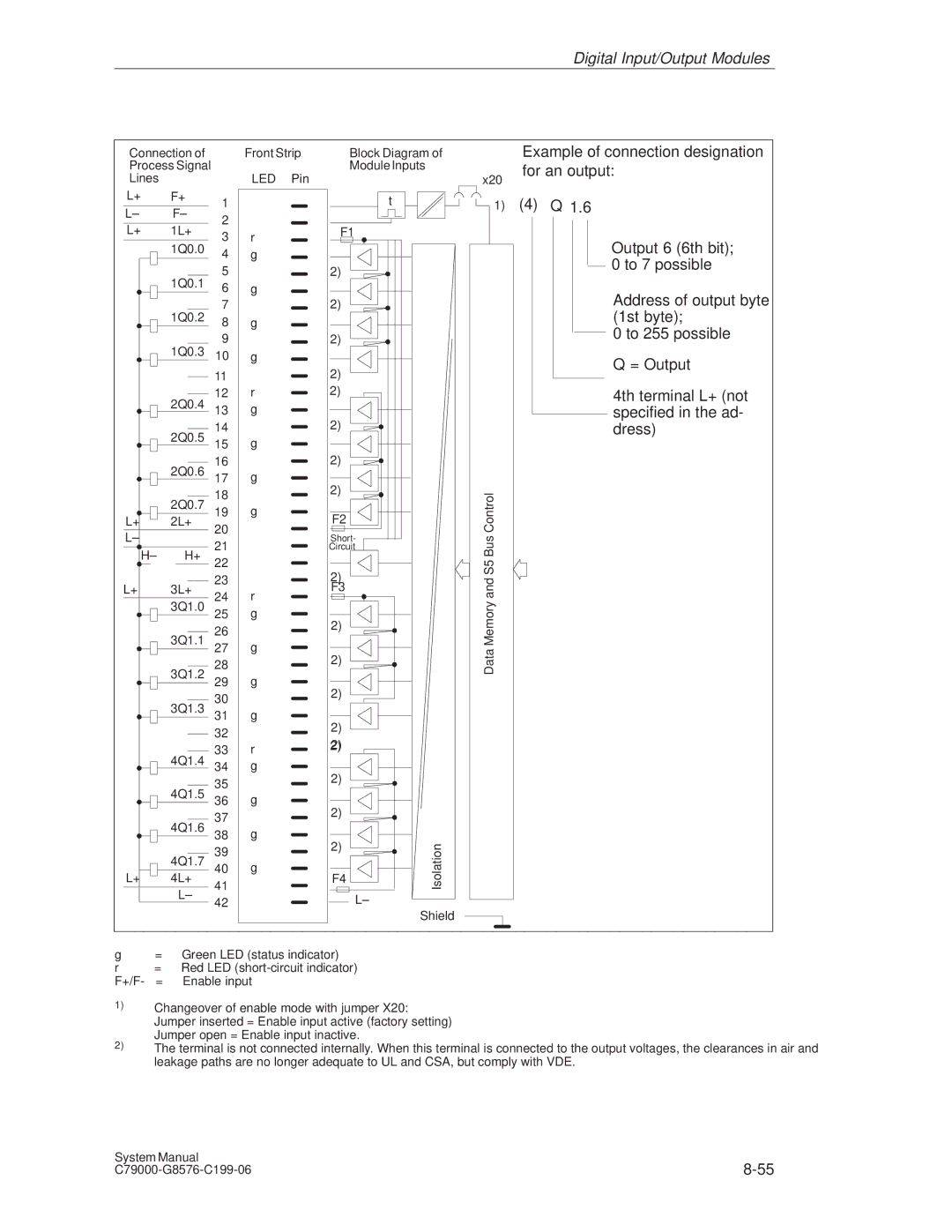
10 6ES5 451-4UA13/4UA14 Digital Output Module
To 255 possible = Output
11 6ES5 453-4UA12 Digital Output Module
Example of connection designation for an output
12 6ES5 454-4UA13/4UA14 Digital Output Module
Mechanical specifications
X20 Data Memory and S5 Bus Control
13 6ES5 455-4UA12 Digital Output Module
X20 2 Q
14 6ES5 456-4UA12 Digital Output Module
Example of connection designation
15 6ES5 456-4UB12 Digital Output Module
1Q0.0 2Q0.1 3Q0.2 4Q0.3
16 6ES5 457-4UA12 Digital Output Module
Block Diagram Module Inputs
17 6ES5 458-4UA12 Digital Output Module
S5 Bus Control
External Suppressor Circuitry for Inductive Load
18 6ES5 458-4UC11 Digital Output Module
Process Signal Module Inputs Lines
Inputs
19 6ES5 482-4UA11 Digital Input/Output Module
Outputs
Synout
Analog Input/Output Modules
Analog Output Modules
Programmable logic controller
Analog Input Modules and Cards
Analog Input Modules
128 to 255 0 to
Address range
Modules are protected by covers on both sides
Function of the Enable Input
Switch, Mode
460 Analog Input Module Design
Acknowledge
Enable Input and Enable Jumper
Configuring
Power Supply
Special Features of the 460 Analog Input Module
Inhibit
Time-Controlled
Program
Basp Output
Subaddress
On Setting Switch Pressed
Cyclic/Selective
Addressing for
Sampling
Removing and Inserting Modules
Remove an analog input/output module as follows
Module with Front Connector
Marking and Labeling of Modules
Marking of Modules and Front Connectors
To 60 V DC 20 mm
Without fan
Sensors
Connection of Sensors
Connection
Current or Voltage
MUX
Connecting a Compensating Box for Thermal E.M.F. Measurement
CH0
24V
Extended Pt
Broken Wire Signal
Broken Wire at Module Reaction, Encoded Value Error Bit E
Standard Pt Range
Four-wire transducer with separate supply voltage
Connecting Transducers
Four-wire transducer with a two-wire transducer card
Measured-Value Representation as Twos Complement
Measured-Value Representation
Digital
Rated input range $ 50 mV
Bit 212 is interpreted as the sign
Measured-Value Representation as Value and Sign
Resistance Thermometers Standard Pt Range
Measured-Value
Representation for
Ohm 10 units
Units Pt 100/ohms
20 mA
Current Measuring Ranges from 4 to
Current Limiting
6ES5 460-4UA13 Analog Input Module
Analog Input/Output Modules
Mode
Range
Labeling of switches on the module cover
Analog Input/Output Modules
ADU
Assignmentstransducer
12 Analog Input Module
463 Analog Input Module Design
Switching off the Enable Input
Timeout QVZ occurs in the CC
Power Supply Load Power Supply
10000 ∝F/40V
Switches should be switched off
Special Features of the 463 Analog Input Module
Module with 4 inputs therefore reserves 8 byte addresses
Module, is given by
Channel number
On Setting Switch Pressed 128
Removing and Inserting Modules
Module
16 Marking and Labeling of Modules
Connecting the Signal Lines
Shunt Resistor
Representation as Value and Sign
Load Voltage
6ES5 463-4UA12 and 6ES5 463-4UB12 Analog Input Modules
Connecting Transducers
Setting the Data Format for the 4 to 20 mA Range
Front Connector Assignments
18 Analog Input Module
465 Analog Input Module Design
Enable Jumper
Configuring
10000 ∝F/40V
Is set
Special Features of the 465 Analog Input Module
Selective Sampling
To AUX Flag
Inputs or outputs reserves 32 byte addresses
20 Labeling of the Addressing Switch
Example
Addressing for
Removing and Inserting Modules
21 Module with Front Connector
22 Marking and Labeling of Modules
Rated Voltage Ule To 60 V DC Mm Operation With fan 40 mm
23 Connecting a Compensating Box
Analog Input/Output Modules
Connecting a Pt
Channel and the value 0 would be encoded
Broken Wire Signal for Resistance Thermometers
Broken Wire at
Module Reaction, Encoded Value Error Bit E
Connecting Transducers
Measured-Value Representation
Measured-Value Representation as Value and Sign
Pt 100 Resistance Thermometers
Ohm 10 units
Short-circuit with two
6ES5 465-4UA12 Analog Input Module
Analog Input/Output Modules
Mode
Mode 50 mV 50 mV 100 mV 1 V 2 mA 500 mV ±
25 Front Connector Assignments
Switches on the board
Special Features of the 466 Analog Input Module
466 Analog Input Module Design
Groups
Current/Voltage
Measurement for
Individual Channel
Channel Group IV Channels 12 to
Switch S5
Switch S7
Channel Group III Channels 8 to
20 mA $ 20 mA $ 1.25 $ 2.5 $ 5 $ 10
Range
Twos complement Value and sign Binary
Setting the Data Format
S9 Switch Setting
Data Format
466-3LA11 Module
Setting the Module Start Address
Module Address
Removing and Inserting Modules
28 Module with Front Connector
29 Marking and Labeling of Modules
Connecting the Signal Lines
Connecting Sensors to the 466 Analog Input Module
Jumper between M+ and M
Differential
Measurement
Compensates for the interference acting on both lines
UCM2
Measured-Value Representation with Various Ranges
OV Overflow bit Error bit Active bit
Signal Status Meaning
Range exceeded Broken wire Not used
Twos Complement Measuring Range 20 mA Bipolar
Measuring Range 20 mA, 0-5 V Unipolar
Measuring range 0-1.25 V and 0-2.5 V unipolar
Binary measuring range $ 5 V, $ 20 mA and $ 10 V bipolar
Binary measuring range $ 1.25 V and $ 2.5 V bipolar
Value and sign measuring range $ 1.25 V and $ 2.5 V bipolar
6ES5 466-3LA11 Analog Input Modules
Analog Input/Output Modules
Front Strip Pin
Voltage-to-ground measurement Differential measurement
Module address
470 Analog Output Module Design
35 Enable Input and Enable Jumper
Configuring
Load Power Supply System Manual
Function block from the ªbasic functionsº package
Special Features of the 470 Analog Output Module
Output, a value is retained
Function Block
Start Address
Addressing for
Removing and Inserting Modules
Remove an analog output module as follows
37 Module with Front Connector
4 1 5
Connecting the Signal Lines
Voltage Outputs
Connecting Loads to the 470 Analog Output Module
41 Connecting Loads
Digital Measured-Value Representation as Twos Complement
Technical Specifications
470-4UB 470-4UA 470-4UC
42 Front Connector Assignments
System Manual C79000-G8576-C199-06
Monitoring Module
Monitoring Module
Data bus
Mode of Operation Block Diagram Address bus
Address Bus
Fault Detection
Data Bus Faults
Faults
Control Line
Resetting
Messages
Removing and Inserting
Installation Possible Configurations
Switch Positions of the Relay Contact
Connecting the Reset Input
Installation Guidelines
Acknowl- edged by module with RDY
Write
10-9
1st MM 2nd MM 3rd MM Last EU
Addressing
Without S5-DOS With S5-DOS
213 D5H 170
S5-115U 128 80H 129 81H 213 D5H 170
128 129 213 170
Setting the Address Switches S1, S2, S3, S4
Setting the Switch S5
Safety test
Power supply
Reset input
Sensor supply for Reset input
Ambient conditions
Address Table
Connector Assignments
M24 V P24 P15
Back- plane conn
11-3
Pin designation of the interrupt signals on the backplane
11-5
Backplane conn
Connector assignments of the backplane for the EU 185U
11-7
11-8
5V/40A power supply units
Connector assignments of the power supply units
Connector
5V/18A power supply units
Plug connector, 37-way, Series D to MIL-C24308
Terminals of the supply lines between the power supply unit
Contacts, Series D to MIL-C24308
Assignments of the backplane connector CPU
Pin Pin Row + 5
Assignments of the backplane connector CPU 928B
Steu Stoppa M 5 V R x D Pero M 24 V M 5
Assignments of the backplane connectorCPU
11-14
11-15
Memw RDY DB 0 DB 1 DB 2 DB 3 DB 4 DB 5 DB 6 DB
Assignments of the backplane connector 923A coordinator
RxD TxD
Assignments of the backplane connector 923C coordinator
11-18
Assignments of the backplane connectors of the IMs
DB13
+5V Shield
+5V
+5V DB12
11-21
+ PEU ± PEU
Assignments of the front blade connectors
11-23
System Manual C79000-G8576-C199-06
Appendix
Central Controllers
For Chapter
Expansion Units
WKF RZF
Power Supply Units
Interface Submodules
CPUs
Memory Cards
Bbytes 6ES5 376-0AA11 6ES5 376-0AA21 6ES5 376-0AA31
Interface Modules
Coordinators
Digital Input/Output Modules Adhesive Label
Front Connectors
Analog Input/Output Modules
Range Card
Features
Range Cards Modules
6ES5 460-4UA13 6ES5 465-4UA12
Catalog ST
Programmable Controllers
Programmers
C79000-G8576-C140 6ES5 998-2EA21
Chapter Overview
Definition
What is ESD?
To overvoltages and thus to any electrostatic discharge
IEC
Electrostatic Charging of Persons
Charging
Its surroundings can be charged electrostatically
Avoid Direct
Ensure Sufficient
Contact
Index
Index
Index-3
Index-4
Index-5
Index-6
Index-7
System Manual C79000-G8576-C199-06
System Manual 6ES5998-0SH21-06
System Manual