4.13 Display assembly | 4 Replacement Procedures |
4.13 Display assembly
Removing the Display assembly
To remove the display assembly, follow the steps below and refer to Figure
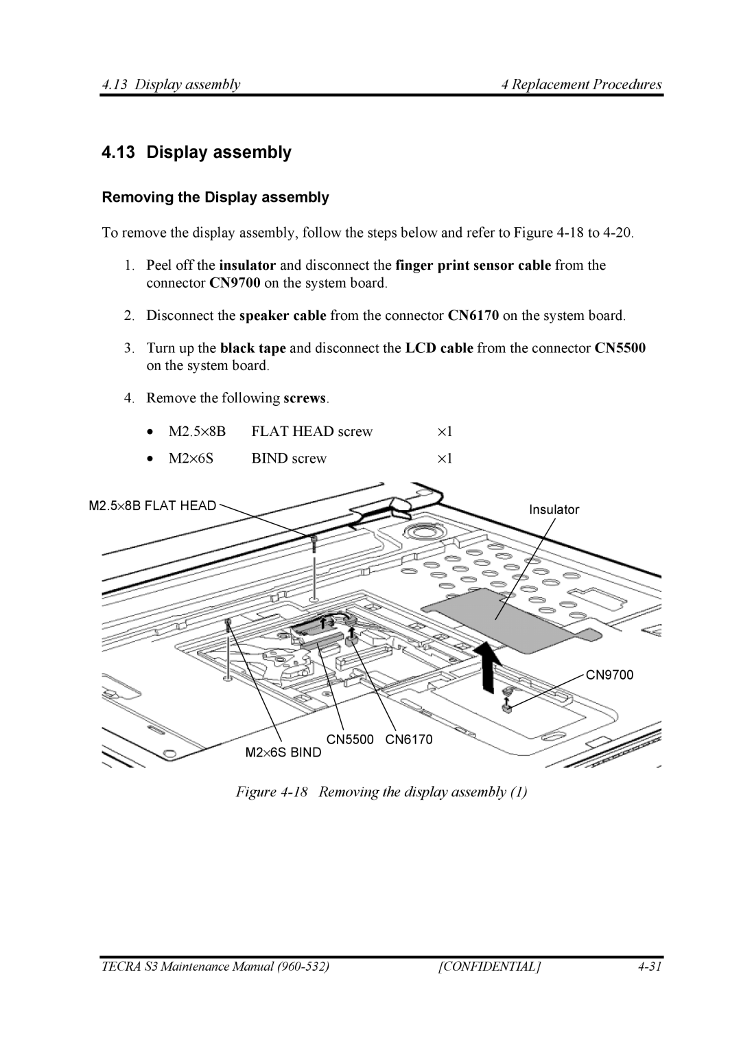
1.Peel off the insulator and disconnect the finger print sensor cable from the connector CN9700 on the system board.
2.Disconnect the speaker cable from the connector CN6170 on the system board.
3.Turn up the black tape and disconnect the LCD cable from the connector CN5500 on the system board.
4.Remove the following screws.
• | M2.5⋅8B | FLAT HEAD screw | ⋅1 | ||
• | M2⋅6S | BIND screw | ⋅1 | ||
|
|
|
| ||
M2.5⋅8B FLAT HEAD |
|
|
|
| |
|
|
| Insulator | ||
|
| ||||
M2⋅6S BIND
CN9700
CN5500 CN6170
Figure 4-18 Removing the display assembly (1)
TECRA S3 Maintenance Manual | [CONFIDENTIAL] |