4.21 GFX board | 4 Replacement Procedures |
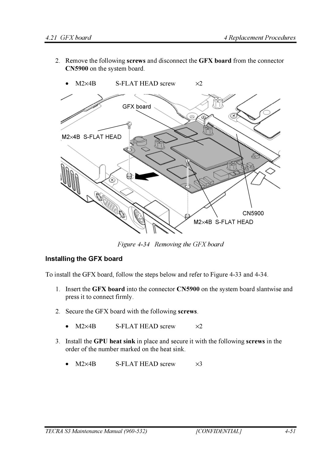
2.Remove the following screws and disconnect the GFX board from the connector CN5900 on the system board.
• M2⋅4B | ⋅2 |
GFX board
M2⋅4B
CN5900
M2⋅4B
Figure 4-34 Removing the GFX board
Installing the GFX board
To install the GFX board, follow the steps below and refer to Figure
1.Insert the GFX board into the connector CN5900 on the system board slantwise and press it to connect firmly.
2.Secure the GFX board with the following screws.
• M2⋅4B | ⋅2 |
3.Install the GPU heat sink in place and secure it with the following screws in the order of the number marked on the heat sink.
• M2⋅4B | ⋅3 |
TECRA S3 Maintenance Manual | [CONFIDENTIAL] |