4 Replacement Procedures | 4.13 Display assembly |
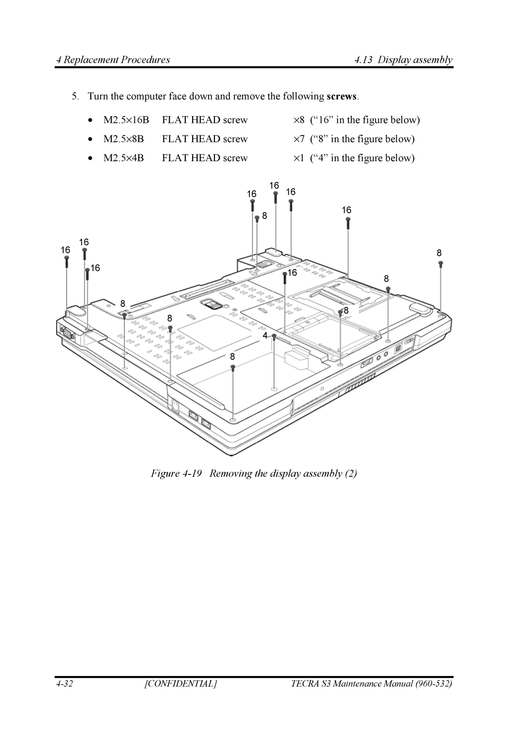
5. Turn the computer face down and remove the following screws.
| • | M2.5⋅16B | FLAT HEAD screw |
| ⋅8 (“16” in the figure below) | |||||
| • | M2.5⋅8B | FLAT HEAD screw |
| ⋅7 | (“8” in the figure below) | ||||
| • | M2.5⋅4B | FLAT HEAD screw |
| ⋅1 | (“4” in the figure below) | ||||
|
|
|
| 16 |
|
|
|
|
|
|
|
|
| 16 | 16 |
|
|
|
|
| |
|
|
|
|
|
|
|
|
|
|
|
|
|
|
| 8 |
|
| 16 |
|
| |
16 | 16 |
|
|
|
|
|
|
|
| |
|
|
|
|
|
|
| ||||
|
|
|
|
| 8 | |||||
16 |
|
|
|
|
|
|
|
|
|
|
|
|
|
|
|
|
|
|
|
|
|
|
| 16 |
|
|
|
| |
|
|
|
|
|
|
| 8 | |||||||
|
|
|
|
| ||||||||||
|
|
|
|
|
|
|
|
|
|
|
|
|
| |
|
|
|
|
|
|
|
|
|
|
|
|
|
|
|
|
| 8 |
|
|
|
|
|
|
|
|
|
|
|
|
|
|
|
|
|
|
|
|
|
|
| 8 |
|
| |
|
|
|
|
|
|
|
|
|
|
|
|
|
| |
|
|
|
| 8 |
|
|
|
|
|
|
| |||
|
|
|
|
|
|
|
|
|
|
|
|
|
| |
|
|
|
|
|
|
|
|
|
|
|
|
|
|
|
|
|
| 4 |
|
|
| ||||||||
|
|
|
|
|
|
|
|
|
|
|
|
|
|
|
|
|
| 8 |
|
|
|
|
|
|
|
| |||
Figure 4-19 Removing the display assembly (2)
[CONFIDENTIAL] | TECRA S3 Maintenance Manual |