Epson Stylus PRO
Page
Precautions
About This Manual
Symbols Used in This Manual
Revision Status
Contents
Operating Principles
Disassembly & Assembly
Maintenance
Product Description
Features
Epson media Slide Bar Resolution Dot Mode Speed
Throughput Speed
Name Code Product
Standard Accessories
Consumable Products & Options
Consumables & Options
Print Area and Speed
Print Specifications
Printing Specifications
Character Specifications
Should be smooth
Paper Specifications
Roll Paper Specifications
Epson Special Paper
Cut-Sheet Availability
CUT Sheet Specifications
Size Dimensions W x H
Supported Cut-Sheet Paper
Printable Area
Optimal Margin Settings
Printable Area
Printable Area
Ink Cartridges
Electrical Specifications
10. Electrical Specifications
Situation Temperature
Environmental Conditions
TEMPERATURE/HUMIDITY
Humidity % Temperature C
Reliability
Condition Vibration Shock
Controller
Vibration & Shock
12. Vibration and Shock
Conformity/Safety Approvals Acoustic Noise
CE Marking
Interfaces
Description
Parallel Interface Compatibility Mode
13. Parallel Interface Specifications
Data Transmission Timing
Parameter Minimum Maximum
Parallel I/F mode Time required
14. Data transmission times
15. Typical tack time
Pin Signal Return Functional Description Name Out
16. Connector Pin Assignments and signals Forward Channel
Pin Signal Name Return Functional Description Out
Parallel Interface Nibble Mode
17. Transmission Specifications
18. Connector Pin Assignments Reverse Channel
19. Transmission Specifications
Parallel interface ECP mode
20. Connector Pin Assignments ECP Mode
Pin #2
21. USB connector pin assignments and signals
Pin no Signal name In/Out Description
4 USB
Preventing Data Transfer Time-Outs
TYPE-B Optional Interface
Interface Selection
Setup Guidelines
Printer Dimensions & Weight
Cutter Specifications
22. Buttons and Functions
Button Function SelecType Power-On Second function Normal
Control Panel
Buttons
LED Indicators
23. LED Indicator Lights
Status Condition
26. Pause Indicator
Indicator Status in Normal Mode
24. Operate Indicator
25. Paper Out Indicator
Display Message Meaning
28. Paper Source Indicator
Control Panel Messages
29. Control Panel Messages
Panel Display Priority
Loading Paper
SelecType Settings
30. SelecType Menus
Display Message For details, see
Printer Setting Menu
31. Printer Setting Menu
Display Message Options
32. Test Print Menu
Test Print Menu
Nozzle check
Status sheet
Printed Value Meaning
33. Cutter Life Value
Detecting Paper Thickness
Paper Configuration Settings
35. Paper Config. Menu
Printer Status Menu
36. Cutter Replace Menu
Cutter Replacement Menu
Head Alignment sections
Head Alignment Menu
Display Messages
Maintenance Request
ADJUST. Patt
37. Head Alignment Menu
Service Requests
38. Service Errors
Service Code Explanation
Following explanations regarding control panel service
Maintenance And Diagnostic Modes
Maintenance Mode
39. Maintenance Mode
40. Maintenance Mode 2 Nvram counter value menu
LCD Message Description Decimal
LCD Message Description
Firmware Update
SELF-DIAGNOSTIC Mode
Information contained in this section is not to be shared
Initialization
Jumper Settings
41. Jumper Settings
Type Number Setting
Transportation Mode
Operating Principles
Part Drive voltage Description
Component List & Illustrations
Print Mechanism Components
Printer Mechanism Components
Epson Stylus Pro
Edge sensor Underneath carriage Control Panel
Carriage Components
Paper Set Lever Rear sensor Front sensor Paper suction Fans
Paper Feed Path & Components
Pump
Main board Power supply Board
Carriage
Description of Components
Carriage Movement
Carriage Linear Encoder Flag Fence Home Position Sensor
Carriage & Carriage Components
Cutter
Screw Cutter height guide
PF Rail
Paper Feed Assembly
Detected Sensor Signal Output Signal Thickness Strength
PAPER-FEEDING-RELATED Sensors
Paper Thickness Detection
Maintenance Assembly
CR Lock HeadCap Assembly Cleaner Pump Assembly
Flushing box Pump
CR Lock Mechanism
Ink Supply Mechanism
INK-RELATED Sensors
Ink Low Sensor
Cover
Motor Driver Front cover Open Cover open Flag
Cover open sensor
Motor Driver
Print Speed
Print Mode Carriage Speed
Printer Mechanism Operation Outline
Carriage Mechanism
17. Platen Gap Control
Platen GAP Mechanism
Setting Setup Gap Position
Determining PG Settings
Platen Gap Settings
Control Panel Command Paper Actual Platen
Paper Feed Mechanism
Yes
Stops
Paper exists? Yes
Black line = paper Detection
InHP? Yes
Left-top edge Right-top edge Perform regular flushing
20. Paper-size detection of leading edge
Epson Stylus Pro Revision B
Summary of Control Circuit Operations
21. C299MAIN Board-Circuit Block Diagram
Name/Code Location Function
Control Circuit Operation
Power Supply Board Summary
PS Board Signal Summary
Signal Name Condition Function
Troubleshooting
Remember
Diagnosing the Problem
Outline
First
Maintenance Errors
Service Errors
Service Errors
Nvram
Troubleshooting Using the Error Messages
LCD Panel Error Messages
LCD message Status Type Refer to
Error Code Description Refer to
Messages That Indicate Service is Necessary
Error Type Message Refer to
Ink Low
LCD
Maintenance Call nnnn
Errors
No Paper Loaded
10. Please Load Paper
Paper Path Command and LED Indicators
PP Command Roll Sheet Auto Cut No Cut
Please Load
13. Paper Not Cut
12. Cover Open
15. Correctly Load Paper
14. Paper Skew
Cause the ink counter to function improperly
16. Return Paper Lever
17. Load Ink Cartridge
18. Replace Ink Cartridge
22. Cannot Print
19. No Cartridge
20. Option I/F Card
21. Remove Paper
Code Description Refer to
Fatal Errors
23. Fatal Error
24. Fatal Error Code List
Errors That Require a Service Technician
Maintenance Call
Service Call
Epson Stylus Pro Revision B
Epson Stylus Pro Revision B
Epson Stylus Pro Revision B
Service Call 0001000D Service Call 0001000E
Service Call 0001000A
Service Call 0001000B
Service Call 0001000C
Service Call 0002000B Mail BOX Memory Error
General Errors
INK LOW
Paper OUT
Cover Open
Load XXX Paper
Load Paper
Paper JAM
Paper not CUT
Paper not Straight
Reload Paper
Please Lower Lever
INK OUT
No INK Cartridge
25. Diagnosing trouble based on printout
Troubleshooting Based on Your Printout
Option I/F Error
Remove Paper
Uneven PRINTING/POOR Resolution
„ Before you uninstall the Main Board or a printhead, make
E When using the Adj.B or C Head Slant as well as
Smudged or Marred Printout Front
Smudged or Marred Printout Reverse Side
White or Black Banding
Disassembly & Assembly
Summary
Disassembly & Assembly Summary 108
Disassembly & Assembly Summary 109
Tool Part Code
Tools
Necessary Tools
Front Bottom
Screw List
Screws
Type Color Description
Disassemble Printer Mechanism
Disassembly Flow
Remove Panel & Housing
Remove Circuit Board
Panel Unit Removal
Removing the Housing
Lever opening cap
Side Cover Removal
Panel Unit
Hook
Side Cover Paper Set Lever Position
Roll Cover One Screw
Screws
One screw on inside of right cover
Three Side Cover Screws
1.4 I/C Holder Cover Removal
One Roll Cover
Two screws
Top Cover Removal
Two Top screws Cover
Top Cover Three screws
Two screws Optional
Rear Cover Removal
Two
Paper Guide L2 Removal
Roll Paper Cover Brake pin
Roll Paper Cover Removal
Roll Paper Cover Two
Spindle support
Front cover Support shaft
Front Cover Removal
Spring catch Ring
Support shaft
Circuit Board Removal
Power Board Removal
Power Supply Board Connectors
Connector # Pins Color Connection
Assy
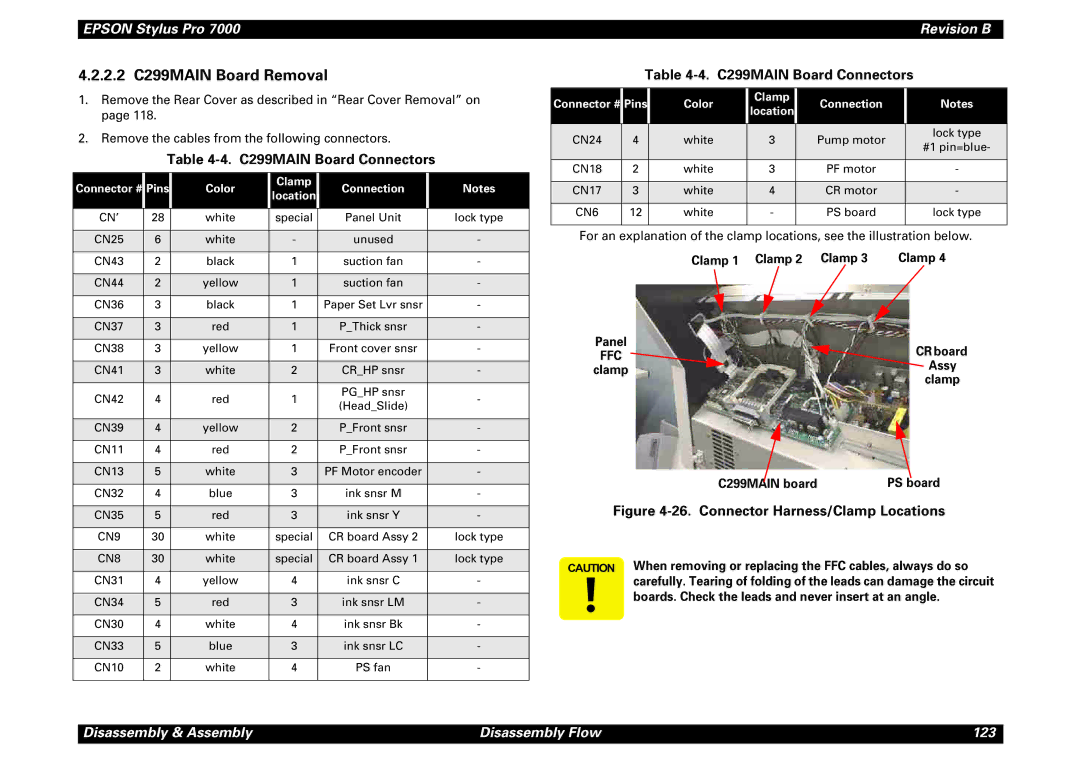
C299MAIN Board Connectors
2.2 C299MAIN Board Removal
Clamp 1 Clamp 2 Clamp
AC Inlet Removal
Disassembly of the AC inlet
„ Do not remove or loosen the screws that secure the CR
Printer Mechanism Disassembly
Replacing the Waste Ink Pads
Two waste ink tubes Flushing Tube Waste ink box clamp
Waste Ink Box
Waste ink Box clamp Three hooks
31. Disassembly of the Waste Ink Box
Suctions fans One screw Fan duct Two
Removing the Suction Fans
Replacing the Printheads
Printer uses two printheads, B Head and C Head,
Carriage Cover Cutter Two
Screwdriver
Ink tubes
Head
Sight of the printhead ID when looking at the ID level
From straight in front, the printhead is not installed
Properly
CR Board
Removing the CR Board Assembly
CR board guide Screw, ground line, and washer Three screws
FFC to printheads
Removing the Cutter Housing
43. Cutter Housing Outer Face
44. Cutter Housing Inner Face
Cutter not
Removing the Cutter Solenoid
Cutter shaft
Cutter cap
One screw PEdge sensor Inner Face
Removing the CR Encoder Sensor
Removing the PEdge Sensor
CR Encoder Sensor One screw
Ink tube cover Two Screws
Removing the Ink Cartridge Holder & Slots
„ Before removing and ink cartridge slot, drain the ink as
Side frame
Two Screws Six screws
Holder Frame Cover-open Sensor One screw
M3x6 M4x6
Holder Frame One screw M3x6 One screw M4x6
Two screws Slot frame
Ink pipes
Removing the Ink Cartridge Sensor
Slot frame Hooks
Slot needle Two Screws M3x6Ink Low Sensor One screw M3x10
Removing the CR Motor/Pulley Assembly
CR Timing Belt Motor Four screws
Belt Shaft
Bracket
Removing the PF Motor Assembly
Reduction Pulley PF Timing
Screws M4x10 Motor PF Motor
Clamp For Panel
Removing the Maintenance Assembly
When you replace the Maintenance Assembly, ink may spill
Harness Maintenance Base
Pump Assembly
Cleaner Head
Maintenance Base Assembly Screws M4x6
Pump Motor Assembly Cap Assembly Flushing Box
Good seal
Pump Motor Assembly Clamp Screws M3x8
Removing the Pump Motor Assembly
Here
Removing the Cap Assembly
Assembly Tubes connect
Cap part
Removing the Pump Assembly
Removing the Cleaner Head
Tweezers Pump Assembly
Screw M3x6 Flushing Box Assembly
Removing the Flushing Box Assembly
Clamp 2/4 Clamp 1/4
Removing the Headslide Sensor Assembly
Clamp on Maintenance Base
SensorScrew AssemblyM3x6
Removing the Crhp Sensor
SensorConnector
Removing the Release Sensor/PTHICK Sensor
Connector Sensor Bracket Screw M3x6 Hooks
Removing the PFRONt Sensor Assembly
Sensor Assembly
Screws M2x8
81. Removing the Paper Guide U
Removing the Prear Sensor Assembly
Screws M2x12 Cover Sensor Cover SW Assembly Holder
Removing the Cover Sensor Assembly
Adjustment
„ Before starting any adjustment procedure, find
Adjustment Outline
Adjustment Tools
Adjustment Tools
Adjustment Items
Service Parts & Required Adjustments
Service Adjustment Items Refer to Operation
Adjustment Steps
Parameter Backup
Requirements for Parameter Backup
Downloading Parameters from PC Card to NEW Board
Backing UP Parameters from Main Board to PC Card
BACKUP/DOWNLOAD Error Recovery
End Error
Range of Backed UP Parameters
„ After updating the firmware, the printer must perform an
Firmware Update
Paper Source + Cut/Eject + Cleaning
Updating Firmware VIA the PC
Updating Firmware from a Memory Card
Self-Diagnostics
Self-Diagnostic Mode Controls
Normal Self-Diagnostic Meaning Function
Self-Diagnostic Menus
Self-Diagnostic Mode Menus
Test Item Description
Do not attempt the D/A Revision or Head Signal test. These
Test Menu
Test Menu Items
Control Panel
Version
Sensor Menu Options
Sensors
Sensor Adjustment
PEdge, PFront, and PRear Sensor Adjustment
Sensor Volume Adjustment
† Pedge Sensor adjustment
† Pfront Sensor † Prear Sensor
Pfront & Prear Volume Adjustment
Encoder
FAN
Elec
Revision and Head Signal
Maintenance Record Items
Adjustment Menu
10. Adjustment Menu Items
Adjustment Item Description
Adjustment Self-Diagnostic Mode Menus 175
ADJ Check Skew
ADJ CAP Position
ADJ Input Rank
Write D/A Value
Printing Pattern Nozzle Check End
Cleaning Standard Print Adj. Pattern
ADJ Check Nozzle
Please Set Paper
ADJ X Head Slant B/C Heads
Head check pattern Bad
Slant Check End
Adjustment Self-Diagnostic Mode Menus 180
Set
ADJ B/C Head Height
Adjustment Self-Diagnostic Mode Menus 182
Correct
ADJ BI-D
Enter Adjust Print Printing Pattern
BiD, XXX, Y, Z O Y=N or M
Bi-D End
Description Number
11. Bi-D Adjustment Items
Adjustment Self-Diagnostic Mode Menus 186
Gap Check End
Head GAP Adjustment
12. Head Gap Adjustment Items
Please Set Paper Printing Pattern Gap XXX Y
Flushing Point 123
Flush Point Adjustment
1000mm
Feed Adjustment
Enter Adjust Print
Printing Pattern Length 1000.0mm
Bottom Length 15.0mm Side Margin
ADJ TOP & Bottom
Bottom margin Top margin Side Margin Feed Direction
Printing Pattern Top Length 0mm
RearSen. Pos +3mm
ADJ Rear Sensor Position
Please Set Cut Sheet
Printing Pattern Paper Width 627mm
Print Adj. Variable
Test Pattern Print
13. Printed Items in the Test Pattern
Print Nozzle Check
Clean Head Drain INK
Adjustment
Minutes
Cleaning Menu
14. Counters Reset by Counter Clear
Counter Clear
Initialize Items
Update Items
Print Menu
Parameter Menu
Adjustment Self-Diagnostic Mode Menus 196
Thick
Mechanism Adjustment
15. Necessary Mechanism Adjustments
Parts Adjustment Necessary Tools Refer to
Secure the screws
CR Timing Belt Tension Adjustment
PF Timing Belt Tension Adjustment
CR Tension Bracket
Trigger arm
Thick Sensor Assembly Adjustment
Paper Feed ↓ + Cut/Eject + Cleaning
16. P Thick Sensor Operation Check
Front Cover LCD Message
Cover Open Sensor Assembly
17. Cover Sensor Assembly Check
Flag Cover switch Holder
USB ID Copy/Backup
Extracting the USB-ID Copy Program
After Extracting the Program
Generating NEW ID & Writing IT to the NEW Board
When performing either of the following procedures, do not
Running the Program
Copying the ID to the NEW Board
Maintenance
General Maintenance Issues
„ Due to the printer’s size, when performing any service or
Product Life Information
Periodic Maintenance Items
Parts That Require Periodic Replacement
When replacing the waste ink pads, replace the pads
Grease and Glue Application
Important Maintenance Items During Service Operations
Items to be Checked During Maintenance/Service
Lubrication and Glue
Appendix
Wiring Diagrams
Electrical Circuit Connector List
Board Connector Description
CN8WHT
Parts List
Parts List
Ref. # Part Name Quantity
CLEANER,HEAD,ASP
Adjust Lever C
Adjust Lever B
Adjust Lever
INK Sensor M Assy
Frame ASSY.,NEEDLE
INK Sensor K Assy
INK Sensor C Assy
Cover LID Assy
Roll Support R Assy
Roll Support L Assy
Branl Panel
Exploded View Diagram
Epson Stylus Pro
Frame Assembly
ASS
EAD ASS
CR ASS
Rame Accessr
Mente ASS
PM-7000C No.7 Rev.01
Cable IDE
Appendix Exploded View Diagram 224
Appendix Exploded View Diagram 225
12. C299MAIN Board Component Layout of Component side
Component Layout
Appendix Component Layout 227
14. C299SUB Board Component Side
Circuit Diagrams
Page