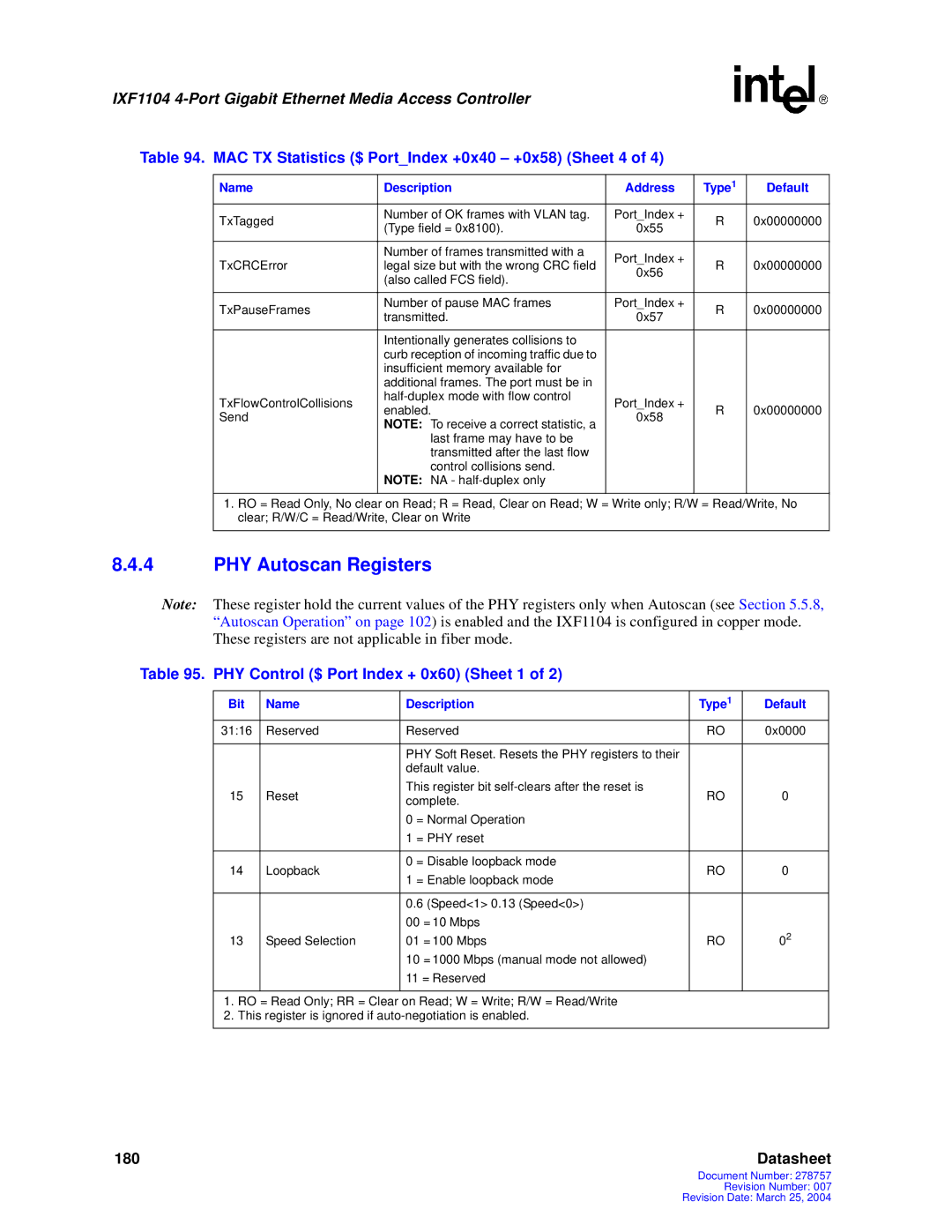
IXF1104 specifications
The Intel IXF1104 is a cutting-edge Network Interface Controller (NIC) designed to meet the needs of high-speed communication in modern networking environments. As the demand for bandwidth-intensive applications continues to grow, Intel's IXF1104 is engineered to deliver exceptional performance, reliability, and scalability, making it an ideal choice for data centers and enterprise networks.One of the main features of the IXF1104 is its support for high-speed Ethernet connectivity, providing up to 100 Gbps throughput. This capability allows organizations to handle large amounts of data traffic efficiently, accommodating everything from cloud computing to big data analytics. The NIC utilizes advanced packet processing technology which ensures minimal latency, enhancing the overall user experience.
The IXF1104 is built on a robust architecture that integrates Intel's latest processing technologies. It incorporates a multi-core processing engine that allows for parallel processing of network packets, improving the handling of simultaneous network requests. This architecture also supports offloading features, freeing up CPU resources for other critical tasks, which optimizes system performance.
In terms of technologies, the IXF1104 supports a variety of standards including Ethernet and Fiber Channel, making it versatile across different networking environments. Its compatibility with industry-standard networking protocols ensures that it can easily integrate into existing frameworks, facilitating seamless upgrades and expansions.
Another significant characteristic of the IXF1104 is its energy efficiency. With Intel’s focus on sustainability, this NIC is designed to consume less power relative to its performance output, thereby reducing overall operational costs for organizations. It employs dynamic power management features that adjust power usage based on demand, which is especially beneficial in large-scale deployments.
Additionally, security features are woven into the IXF1104 design, protecting sensitive data from potential threats. Hardware-based security functions, including encryption capabilities and secure boot processes, ensure that the NIC can safeguard data integrity against unauthorized access.
Overall, the Intel IXF1104 stands out in the crowded NIC market by offering high-performance capabilities, energy efficiency, and robust security features. Its combination of advanced technologies and characteristics positions it as a strategic asset for modern networks, empowering organizations to achieve their connectivity and performance goals in an increasingly data-driven world.

