IXF1104
8.3Per Port Registers
Section 8.4 covers all of the registers that are replicated in each port of the IXF1104. These registers perform an identical function in each port.
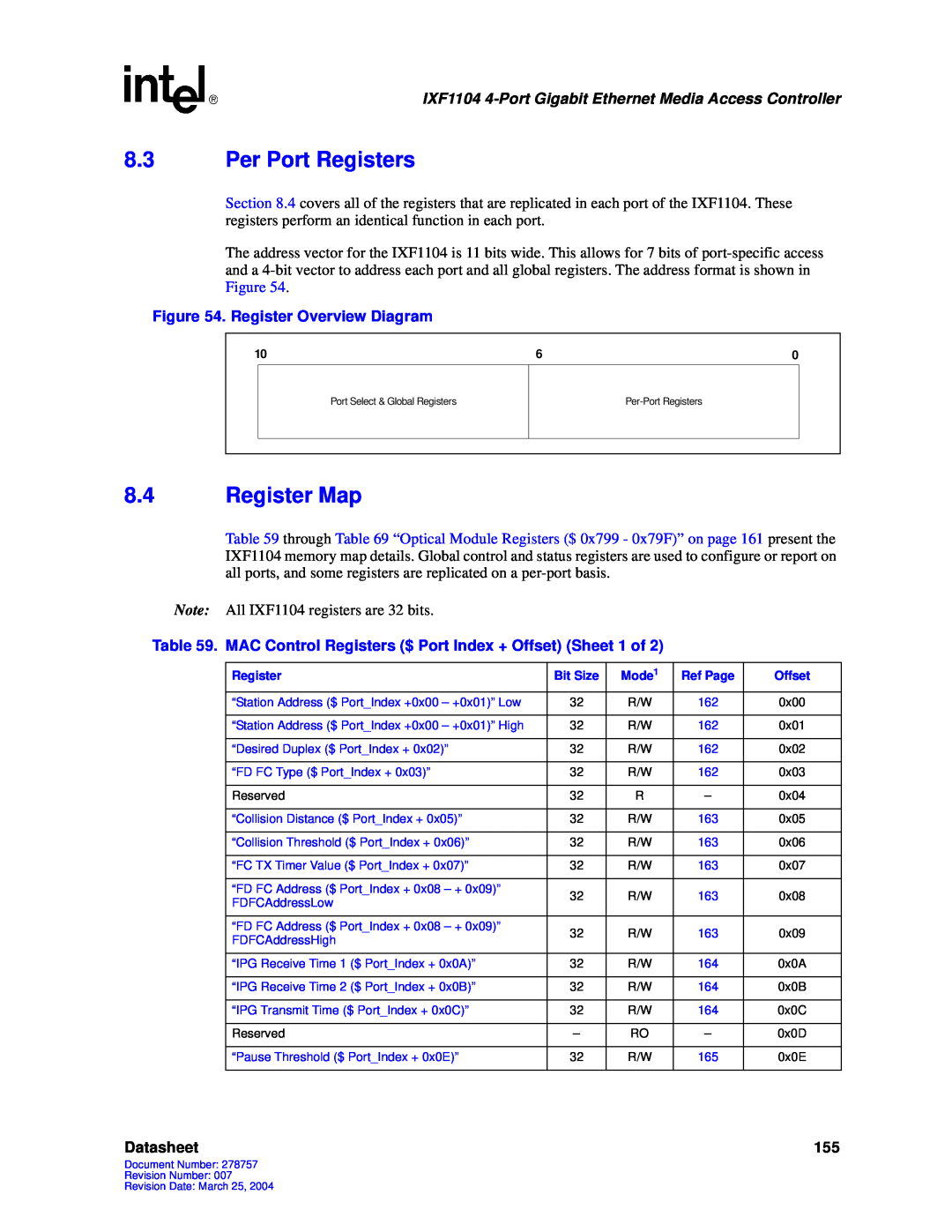
The address vector for the IXF1104 is 11 bits wide. This allows for 7 bits of
Figure 54. Register Overview Diagram
10 | 6 | 0 |
Port Select & Global Registers
8.4Register Map
Table 59 through Table 69 “Optical Module Registers ($ 0x799 - 0x79F)” on page 161 present the IXF1104 memory map details. Global control and status registers are used to configure or report on all ports, and some registers are replicated on a
Note: All IXF1104 registers are 32 bits.
Table 59. MAC Control Registers ($ Port Index + Offset) (Sheet 1 of 2)
Register | Bit Size | Mode1 | Ref Page | Offset | |
|
|
|
|
| |
“Station Address ($ Port_Index +0x00 – +0x01)” Low | 32 | R/W | 162 | 0x00 | |
|
|
|
|
| |
“Station Address ($ Port_Index +0x00 – +0x01)” High | 32 | R/W | 162 | 0x01 | |
|
|
|
|
| |
“Desired Duplex ($ Port_Index + 0x02)” | 32 | R/W | 162 | 0x02 | |
|
|
|
|
| |
“FD FC Type ($ Port_Index + 0x03)” | 32 | R/W | 162 | 0x03 | |
|
|
|
|
| |
Reserved | 32 | R | – | 0x04 | |
|
|
|
|
| |
“Collision Distance ($ Port_Index + 0x05)” | 32 | R/W | 163 | 0x05 | |
|
|
|
|
| |
“Collision Threshold ($ Port_Index + 0x06)” | 32 | R/W | 163 | 0x06 | |
|
|
|
|
| |
“FC TX Timer Value ($ Port_Index + 0x07)” | 32 | R/W | 163 | 0x07 | |
|
|
|
|
| |
“FD FC Address ($ Port_Index + 0x08 – + 0x09)” | 32 | R/W | 163 | 0x08 | |
FDFCAddressLow | |||||
|
|
|
| ||
|
|
|
|
| |
“FD FC Address ($ Port_Index + 0x08 – + 0x09)” | 32 | R/W | 163 | 0x09 | |
FDFCAddressHigh | |||||
|
|
|
| ||
|
|
|
|
| |
“IPG Receive Time 1 ($ Port_Index + 0x0A)” | 32 | R/W | 164 | 0x0A | |
|
|
|
|
| |
“IPG Receive Time 2 ($ Port_Index + 0x0B)” | 32 | R/W | 164 | 0x0B | |
|
|
|
|
| |
“IPG Transmit Time ($ Port_Index + 0x0C)” | 32 | R/W | 164 | 0x0C | |
|
|
|
|
| |
Reserved | – | RO | – | 0x0D | |
|
|
|
|
| |
“Pause Threshold ($ Port_Index + 0x0E)” | 32 | R/W | 165 | 0x0E | |
|
|
|
|
|
Datasheet | 155 |
Document Number: 278757
Revision Number: 007
Revision Date: March 25, 2004