1.Prepare your system for upgrade. See Preparing Your System for Disassembly and Reassembly described earlier in this chapter.
2.Remove the
3.Define the slot in which a board is installed and remove the connector cap of the slot.
IMPORTANT: Keep the removed connector cap carefully.
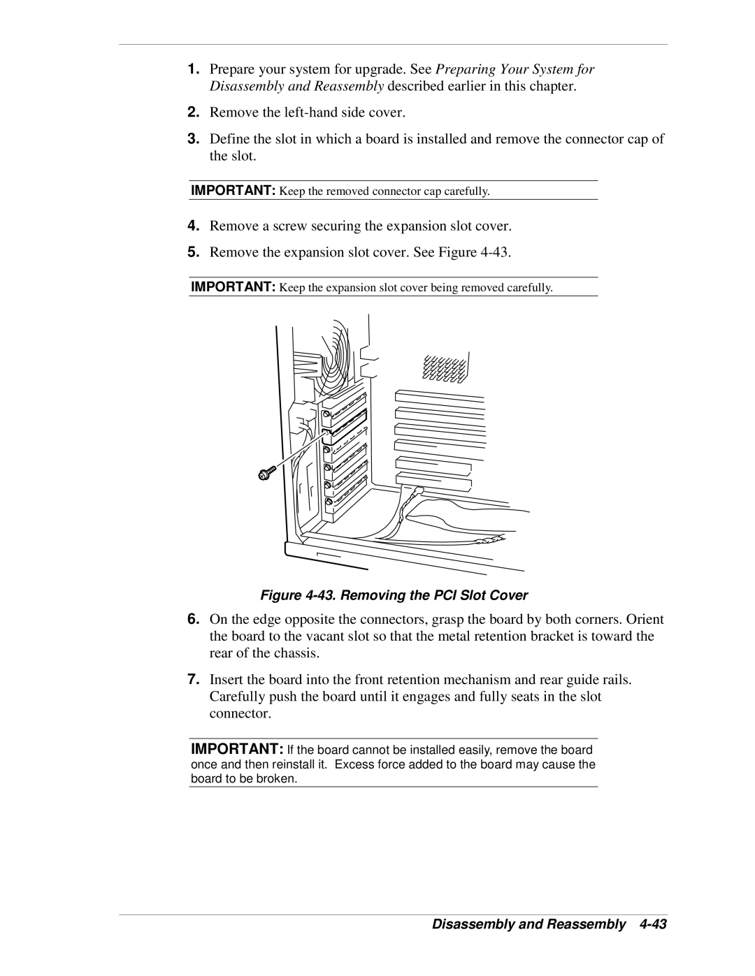
4.Remove a screw securing the expansion slot cover.
5.Remove the expansion slot cover. See Figure
IMPORTANT: Keep the expansion slot cover being removed carefully.
Figure 4-43. Removing the PCI Slot Cover
6.On the edge opposite the connectors, grasp the board by both corners. Orient the board to the vacant slot so that the metal retention bracket is toward the rear of the chassis.
7.Insert the board into the front retention mechanism and rear guide rails. Carefully push the board until it engages and fully seats in the slot connector.
IMPORTANT: If the board cannot be installed easily, remove the board once and then reinstall it. Excess force added to the board may cause the board to be broken.