Removing and Installing a Processor
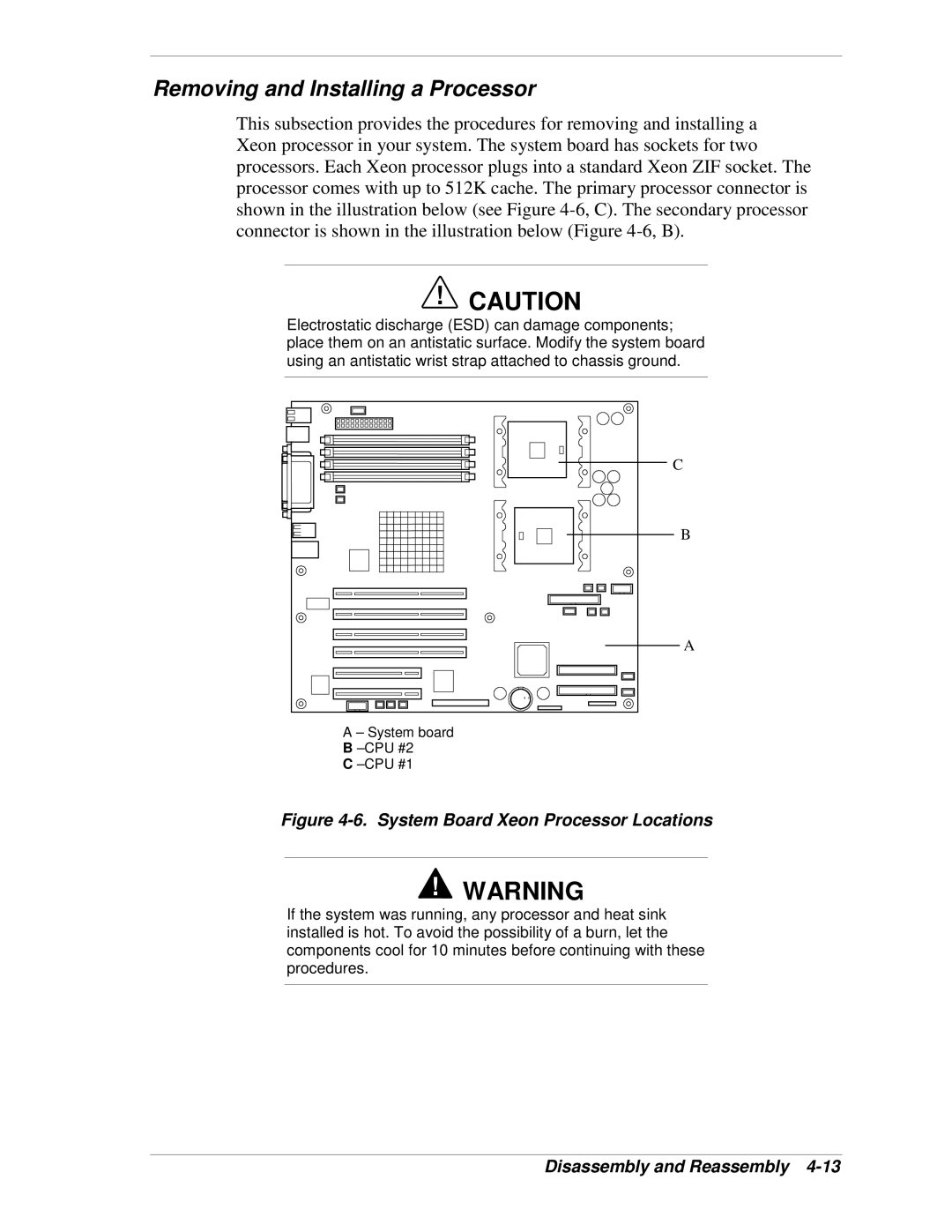
This subsection provides the procedures for removing and installing a Xeon processor in your system. The system board has sockets for two processors. Each Xeon processor plugs into a standard Xeon ZIF socket. The processor comes with up to 512K cache. The primary processor connector is shown in the illustration below (see Figure
!CAUTION
Electrostatic discharge (ESD) can damage components; place them on an antistatic surface. Modify the system board using an antistatic wrist strap attached to chassis ground.
C |
B |
A |
A – System board |
B |
C |
Figure 4-6. System Board Xeon Processor Locations
!WARNING
If the system was running, any processor and heat sink installed is hot. To avoid the possibility of a burn, let the components cool for 10 minutes before continuing with these procedures.