Figure 4-16. Removing the DIMM Connector Cover
11.Holding a DIMM module only by the edges, remove it from its antistatic package.
!CAUTION
Observe static precautions. Use an antistatic wrist strap.
Hold the DIMM only by its edges.
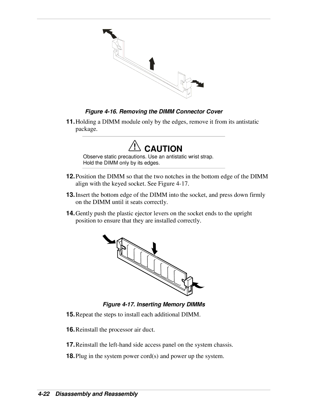
12.Position the DIMM so that the two notches in the bottom edge of the DIMM align with the keyed socket. See Figure
13.Insert the bottom edge of the DIMM into the socket, and press down firmly on the DIMM until it seats correctly.
14.Gently push the plastic ejector levers on the socket ends to the upright position to ensure that they are installed correctly.
Figure 4-17. Inserting Memory DIMMs
15.Repeat the steps to install each additional DIMM.
16.Reinstall the processor air duct.
17.Reinstall the
18.Plug in the system power cord(s) and power up the system.