Disk Array Configuration of Built-in
Hard Disks
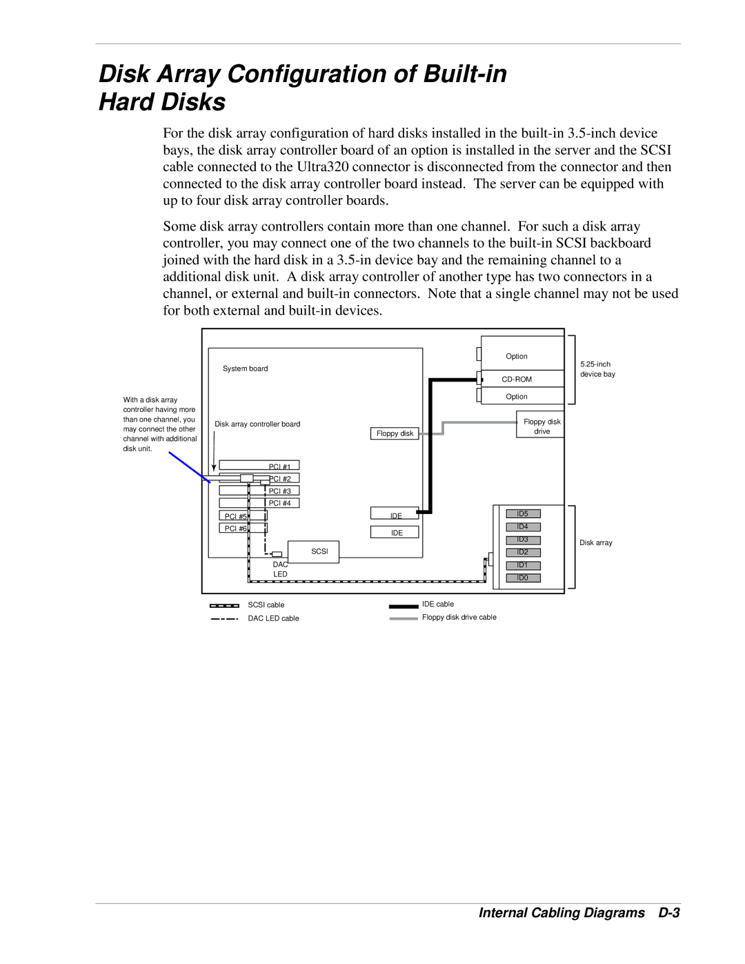
For the disk array configuration of hard disks installed in the
Some disk array controllers contain more than one channel. For such a disk array controller, you may connect one of the two channels to the
With a disk array controller having more than one channel, you may connect the other channel with additional disk unit.
System board |
|
Disk array controller board | Floppy disk |
| |
PCI #1 |
|
PCI #2 |
|
PCI #3 |
|
PCI #4 |
|
PCI #5 | IDE |
PCI #6 | IDE |
| |
| SCSI |
DAC |
|
LED |
|
Option
Option
Floppy disk
drive
ID5
ID4
ID3
ID2
ID1
ID0
Disk array
SCSI cable |
| IDE cable |
| ||
DAC LED cable |
| Floppy disk drive cable |
|