11.Tag and remove any PCI option boards installed on the system board. See PCI Boards earlier in this chapter. Save the PCI option boards for reassembly.
![]() Note: The PCI option boards must be reinstalled in the same slots when you reassemble the system.
Note: The PCI option boards must be reinstalled in the same slots when you reassemble the system.
12.Tag and disconnect all the power, signal, and fan cable connectors from their mating connectors on the system board.
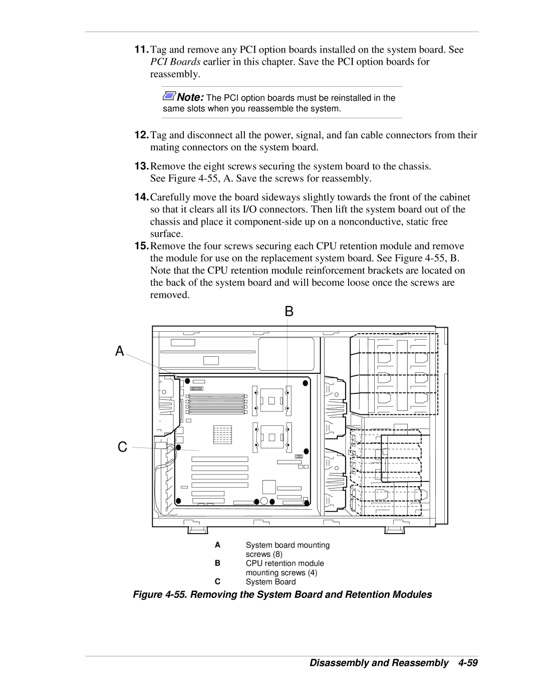
13.Remove the eight screws securing the system board to the chassis. See Figure
14.Carefully move the board sideways slightly towards the front of the cabinet so that it clears all its I/O connectors. Then lift the system board out of the chassis and place it
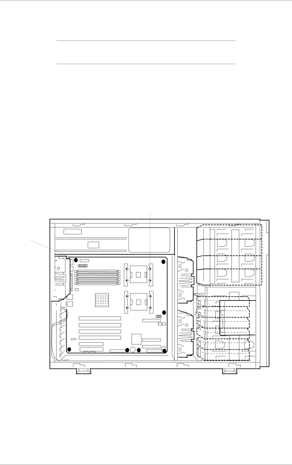
15.Remove the four screws securing each CPU retention module and remove the module for use on the replacement system board. See Figure
B |
A |
C ![]()
ASystem board mounting screws (8)
BCPU retention module mounting screws (4)
CSystem Board