POST Error Code Hardware References
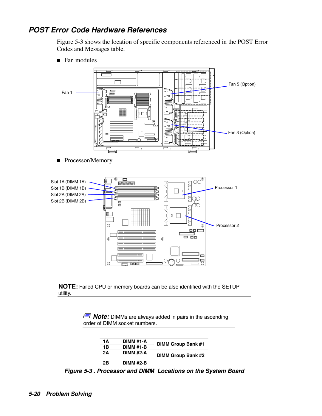
Figure 5-3 shows the location of specific components referenced in the POST Error Codes and Messages table.
!Fan modules
Fan 1 |
! Processor/Memory |
Fan 5 (Option)
Fan 3 (Option)
Slot 1A (DIMM 1A)
Slot 1B (DIMM 1B)
Slot 2A (DIMM 2A)
Slot 2B (DIMM 2B)
Processor 1
Processor 2
NOTE: Failed CPU or memory boards can be also identified with the SETUP utility.
![]() Note: DIMMs are always added in pairs in the ascending order of DIMM socket numbers.
Note: DIMMs are always added in pairs in the ascending order of DIMM socket numbers.
1A | DIMM | DIMM Group Bank #1 | |
1B | DIMM | ||
| |||
2A | DIMM | DIMM Group Bank #2 | |
|
| ||
|
|
| |
2B | DIMM |
|