4.Insert the tabs into holes on the frame of the server, and push the cooling fan unit toward the frame. See Figure
Figure 4-35. Securing the Fan Unit
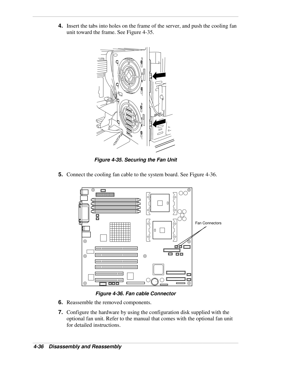
5.Connect the cooling fan cable to the system board. See Figure
Fan Connectors
Figure 4-36. Fan cable Connector
6.Reassemble the removed components.
7.Configure the hardware by using the configuration disk supplied with the optional fan unit. Refer to the manual that comes with the optional fan unit for detailed instructions.