5.Tag and disconnect the LED/Switch Assembly cable (Figure
Intrusion Switch Assembly
Your server system includes two chassis intrusion switches that are located on the front and rear of the system chassis. The switches monitor the front door being opened and the
![]() Note: The intrusion switch assembly consists of two intrusion switches with cables and a single cable connector.
Note: The intrusion switch assembly consists of two intrusion switches with cables and a single cable connector.
To remove the intrusion switch assembly (see Figure
1.Prepare your system for disassembly. See Preparing Your System for Disassembly and Reassembly earlier in this chapter.
2.Remove the
3.Tag and disconnect the intrusion switch cable from its mating connector on the system board. See Figure
4.Remove the intrusion switch located on the front and the switch located at the rear of the chassis. See Figure
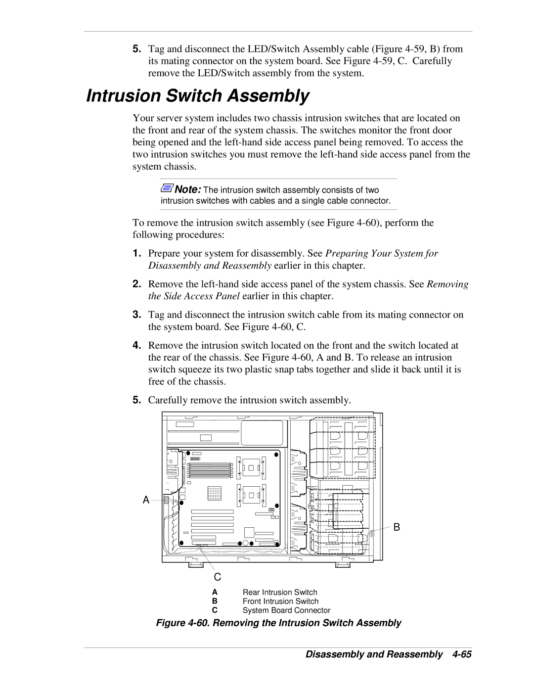
5.Carefully remove the intrusion switch assembly.
A
B
C
ARear Intrusion Switch
BFront Intrusion Switch
CSystem Board Connector