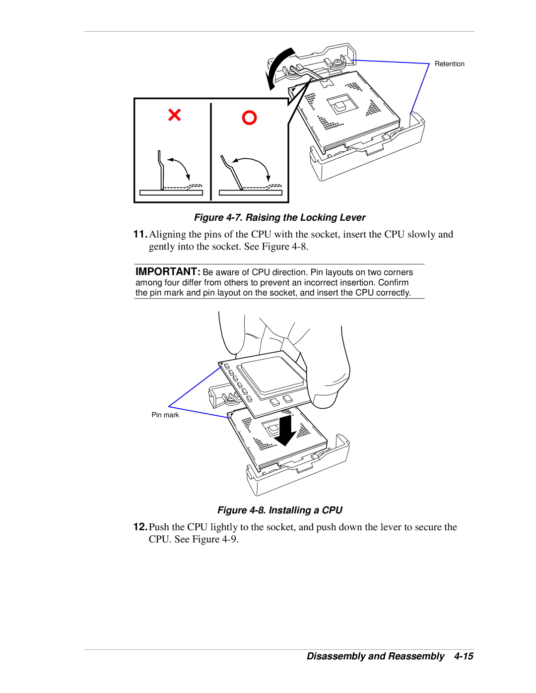
Retention
Figure 4-7. Raising the Locking Lever
11.Aligning the pins of the CPU with the socket, insert the CPU slowly and gently into the socket. See Figure
IMPORTANT: Be aware of CPU direction. Pin layouts on two corners among four differ from others to prevent an incorrect insertion. Confirm the pin mark and pin layout on the socket, and insert the CPU correctly.
Pin mark
Figure 4-8. Installing a CPU
12.Push the CPU lightly to the socket, and push down the lever to secure the CPU. See Figure