10.Snap the replacement I/O shield into place in the rear panel.
11.Install the system board following procedures previously described in this chapter.
12.Install the
LED/Switch Assembly
Your server system contains a front panel that houses the LED/switch assembly. You must open the front bezel to access the front panel. To remove the front panel LED/switch assembly, perform the following procedures:
1.Prepare your system for disassembly. See Preparing Your System for Disassembly and Reassembly earlier in this chapter.
2.Remove the
3.Remove the front panel following procedures previously described in this chapter. See Front Panel earlier in this chapter.
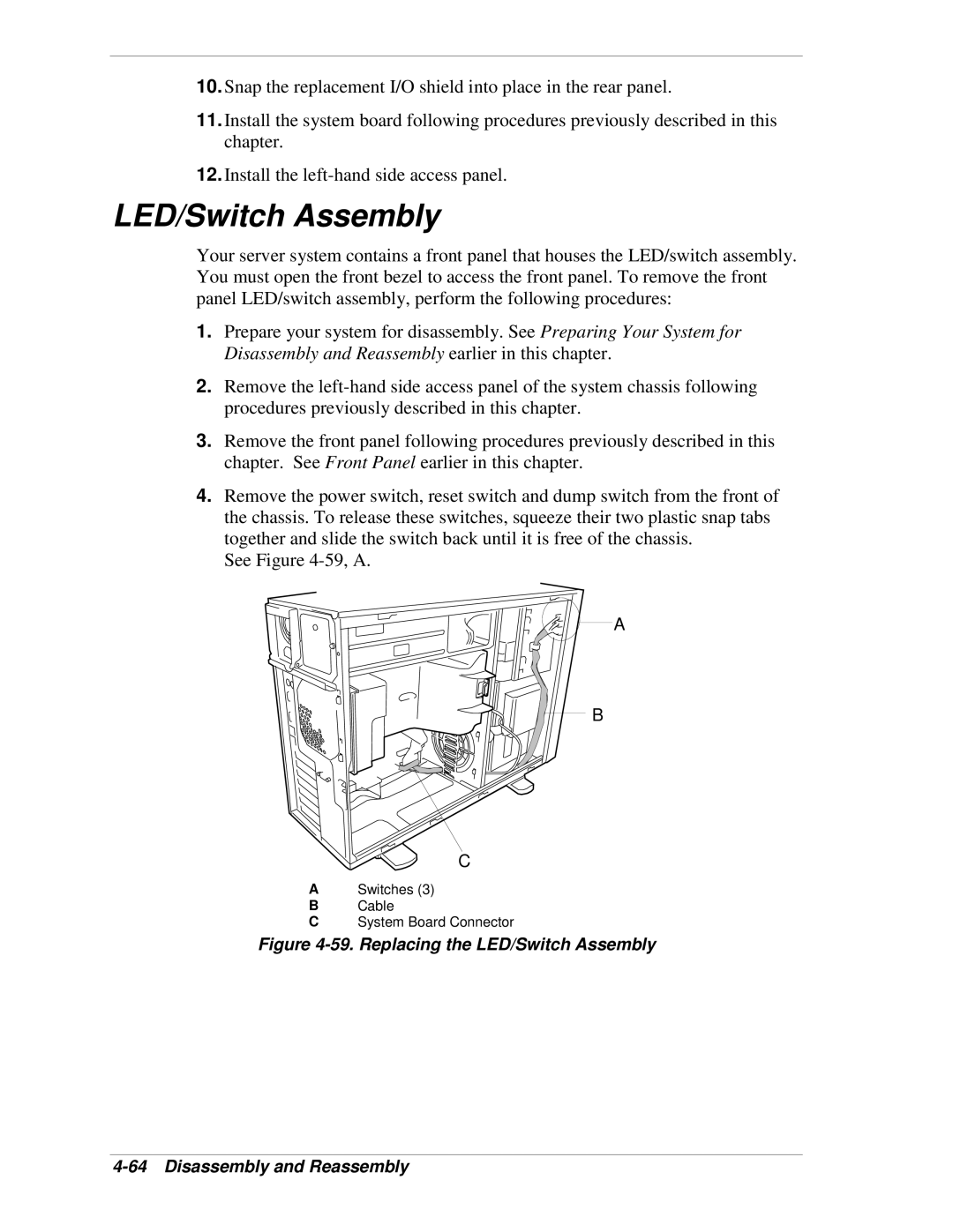
4.Remove the power switch, reset switch and dump switch from the front of the chassis. To release these switches, squeeze their two plastic snap tabs together and slide the switch back until it is free of the chassis.
See Figure
![]() A
A
B
C
ASwitches (3)
BCable
CSystem Board Connector