30 HP 230/460V
Safety Instructions
Operating Precautions
Page
Page
Page
Contents
Options
Troubleshooting & Maintenance
460V Class 1 ~ 30HP
230V Class 1 ~ 30HP
460V Class 40 ~ 100HP
Common Features Specification
Iii
Page
Environmental Conditions
Inspection
Mounting
075 10 HP 550 75 HP
Installation
Other Precautions
Frame
Dimensions
Blank
Frame # 3 15 ~ 20 HP Frame # 4 25 ~ 30 HP
Blank
230/460 50/60 Hz
Basic Wiring
DC Bus Choke
DB Resistor
Symbols Functions
Power Terminals
Type B Configuration
Installation Type a Configuration
P N B1 B2 U Phase Power Input
N B1 B2
Dynamic Braking Unit Dynamic Braking Resistor DC Bus Choke
Installation Type C Configuration
Grounding
Installation Wiring Power Terminals Wiring Precautions
Shorting terminals may cause internal damage to inverter
Motor should be connected to the U, V, and W terminals
Installation Wires and Terminal Lugs
Power and Motor Connection B1 B2 U Phase Power Input
Control Terminals
Type Symbol Name Description
30A 30C 30B AXA AXC
JOG RST
External Sequence Inverter Circuitry
Installation Wiring Control Terminals Wiring Precautions
Control Circuit Terminal
Keypad Connector
Installation Keypad Connection
Installation
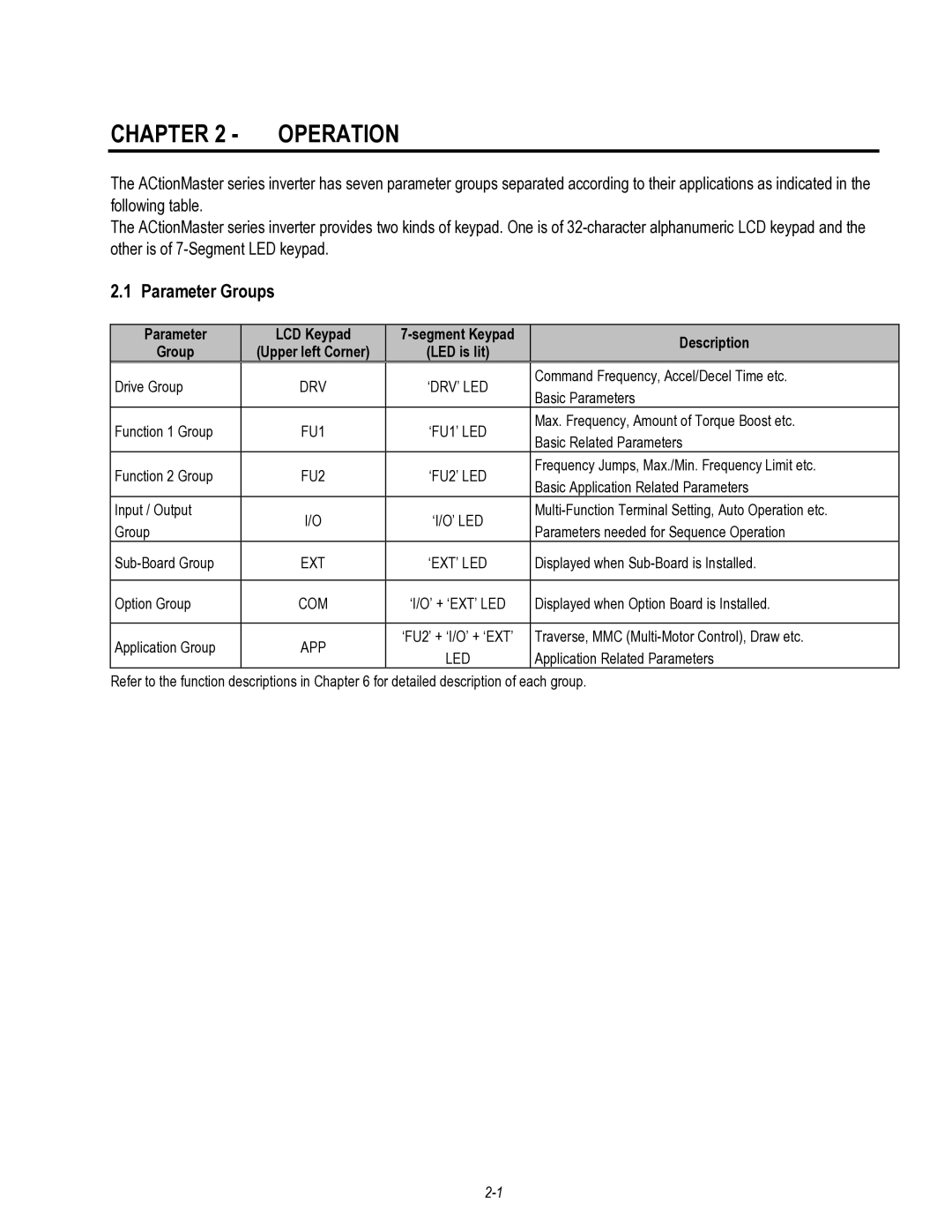
Parameter LCD Keypad Segment Keypad Description Group
Parameter Groups
Operation
LCD Keypad
Displays Description
Operation LCD Keypad Display
00 Hz
Operation Procedure for Setting Data LCD Keypad
Drive Group FU1 Group FU2 Group
Operation Parameter Navigation LCD Keypad
Parameter Group Description
7-Segment Keypad
Segment display Encoder knob
Display Description
Operation 1 7-Segment Keypad Display
First digit
Second digit
I/O Group
FUN1 Group
FUN2 Group
FU1 Group FU2 Group
Operation Parameter Navigation 7-Segment Keypad
Operation Method
Operation Method Function Function Setting
Keypad and Control
Terminals
Operation
Page
QUICK-START Procedures
Quick-Start Procedures
Operation using Keypad
LCD Display Segment Display
LCD Press Prog key Seg PressPROG/ENT key
2 W
Operation using Control Terminals
LCD Display
00 STP 00Hz DRV Drive mode 03 Fx/Rx-1 Keypad DRV Freq mode
Operation using Keypad and Control Terminals
Frequency set by External Source and Run/Stop by Keypad
LCD Press ENT key Seg Press PROG/ENT key
DRV Cmd. freq 00 0.00Hz 00 60.00Hz
00 STP 00Hz
LCD Press ENT key to save the data
SegPress PROG/ENT key to save the data
Page
Basic function parameter setting
Function Setting
Common parameter setting
Parameter Name Code Description
Slip compensation
Function Settings F + PG control
Auto-tuning of motor constant
For V/F, Slip compen , SensorlessS, SensorlessT
Function Settings FU2-40 Description
For VectorSPD, VectorT
Sensorless vector control
F control Parameter Name Code Description
Function Settings
Advanced function 1 setting
Status Code Description
Function Settings Sensorless vector control
Vector control VectorSPD, VectorTRQ
Parameters to view motor and inverter status
Starting / Accel/ Decel / Stopping pattern setting
Protection & fault detection level setting
Speed Signal Applied speed value
Advanced function 2 setting 1 PID operation
Jog and Multi-speed operation
Speed-H Speed-M Speed-L
Energy-saving operation
Function Settings Auto sequence operation
Operation condition
Wiring
Operation Examples
Set it to 0 KeyPad
DRV-5
Operation Example 2nd motor operation
RST AXA
Operation VectorSPD Control Example
Operation Examples
Drive Group DRV
LCD keypad
Parameter List
Function 1 Group FU1
Fwd boost
Limit Hi
Rev boost
Pattern
FU1-99 Return Code Not available
Function 2 Group FU2
Code Description Keypad Display Setting Range Units Factory
Auto tuning
Retry Delay
SS blk time
Pole number
SL I-gain
SL P-gain
PID Ref
PID Out Dir
RPM factor
DB mode
Version
Para. Read
Input/Output Group I/O
P3 define
P2 define
Status
Out status
Segment
Auto mode
Relay mode
Inv No
Baud rate
External Group EXT
P5 define
V2 mode
P6 define
V2 filter
Pulse set
FeedBack
Pulse num
Pulse
LM adjust
LM mode
AM1 mode
AM1 adjust
Communication Group COM
Default
Application Group APP
App Mode
Trv. Scr
Trv. Amp
Trv Off Hi
Trv Off Lo
AutoEx-intv
AutoCh-Mode
Sub-Board Selection Guide According To Function
Parameter List
Page
Monitoring function setting
Digital frequency setting
Setting the DRV-04 Frequency or Torque Mode
Cmd. Freq 00 Hz
10.0
DRV-01 Acceleration Time
Parameter Description DRV
Acc. time
20.0
DRV-03 Drive Mode Run/Stop Method
DRV-02 Deceleration Time
Keypad-1
Freq mode
Setting Range Description
10.00
DRV-05 ~ DRV-07 Step Frequency 1 ~
DRV-08 Output Current
DRV-12 Fault Display
DRV-09 Motor Speed
DRV-10 DC Link Voltage
DRV-13 Motor Direction Set 7-Segment Keypad
DRV-14 Command/Output Frequency Display LCD Keypad
130
DRV-15 Reference/Feedback Frequency Display LCD Keypad
Parameter Description DRV
FU1-05 Acceleration Pattern FU1-06 Deceleration Pattern
FU1-00 Jump to Desired Code #
FU1-03 Run Prevention
FU1 Stop mode Decel
FU1-07 Stop Mode
Parameter description FU1
Decel
FU1 DcBlk time 10 sec
FU1 DcBr freq 00 Hz
FU1 DcBr value 50 %
FU1
FU1 DcSt value 50 %
FU1-14 Pre-excitation Time
FU1 DcSt time Sec
FU1 PreExTime Sec
1000
FU1-15 Hold Time
FU1-16 Pre-excitation Current
00.0
FU1 F-limit Lo
FU1 Freq limit
FU1 F-limit Hi
60.00 Hz
FU1 V/F pattern Linear
FU1-29 Volts/Hz Pattern
15.00
FU1-30 ~ FU1-37 User V/F Frequency and Voltage
100
FU1-38 Output Voltage Adjustment
FU1-39 Energy Save Level
150
FU1 ETH
FU1-54 Overload Warning Level FU1-55 Overload Warning Time
FU1 OL level
FU1 Motor type Self-cool
000
180
St bit
FU1-99 Return Code 7-Segment Keypad
990
Page
Parameter description FU1
FU2-02 Previous Fault History
FU2-01 Previous Fault History
FU2-03 Previous Fault History
FU2-04 Previous Fault History
FU2-10 ~ FU2-16 Frequency Jump
FU2-07 Dwell Frequency FU2-08 Dwell Time
FU2-19 Phase Loss Protection Select
FU2-19 Input/Output Phase Loss Protection Bit Set
FU2-20 Power on Start Selection
0000
FU2-21 Restart After Fault Reset
RST restart
FU2Speed Search
FU2-22 Speed Search Select
FU2 SS blk time Sec
FU2-28 Speed search hold time
FU2Motor select 75kW
75 kW
FU2-38 Carrier Frequency
Control
FU2-39 Control mode selection
FU2Control mode
Detail Tuning Method for Sensorless Vector Control
29.03
FU2-40 ~ 44 Auto tuning
171
32767
3276
FU2 SL P-gain
FU2-47 PID Operation Selection
100.0
300.0
30.0
Parameter Description FU2
Process PID Control
FU2-69 Accel/Decel Change Frequency
FU2-72 Power On Display
FU2-70 Reference Frequency for Accel/Decel
FU2-71 Accel/Decel Time Scale
FU2-73 User display selection
FU2-75 DB Dynamic Braking Resistor Mode Selection
FU2-74 Gain for Motor Speed Display
FU2-76 Duty of DB Dynamic Braking Resistor
FU2-81 ~ FU2-90 2nd Motor Related Functions
FU2-79 Software Version
FU2-91 Parameter Read FU2-92 Parameter Write
Parameter Upload Parameter Download
FU2-94 Parameter Write Protection
FU2-93 Parameter Initialize
FU2-99 Return Code 7-Segment Keypad
Para. init
Parameter Description FU2
06 ~ I/O-10 Analog Current Input I Signal Adjustment
01 ~ I/O-05 Analog Voltage Input V1 Signal Adjustment
Input/Output Group I/O I/O-00 Jump to Desired Code #
Parameter description I/O
20.00
11 Criteria for Analog Input Signal Loss
13 Multi-function Input Terminal ‘P2’ Define
12 Multi-function Input Terminal ‘P1’ Define
14 Multi-function Input Terminal ‘P3’ Define
Speed-L, Speed-M, Speed-H
Parameter Speed-H Speed-M Speed-L
XCEL-L, XCEL-M, XCEL-H
Code
Accel/Decel Parameter XCEL-H XCEL-M
Up, Down
Parameter Description I/O Dc-brake
Exchange
Open-loop
Parameter Description I/O Wire ITerm Clear
Main-drive
Analog hold
Gain2
Xcel stop Hold step
SEQ-L, SEQ-M, SEQ-H
Manual
Segment Keypad Display
LCD Keypad Display
15 Terminal Input Status
16 Terminal Output Status
21 ~ I/O-24 Step Frequency 4, 5, 6
40 FM Frequency Meter Output 41 FM Adjustment
40.00
30.00
43 FDT Bandwidth
42 FDT Frequency Detection Level
44 Multi-function Auxiliary Contact Output
Define AXA-AXC
FDT-2
FDT-1
FDT-3
FDT-4
Stall
FDT-5
IOL
Parameter Description I/O Stop
Lost Command
INV line, Comm line
Ssearch
MMC
45 Fault Output Relay 30A, 30B, 30C
010
9600
46 Inverter Number 47 Baud Rate
Auto B
Parameter Description I/O Auto-A
Parameter Description I/O
Parameter Description I/O
Parameter Description EXT
EXT-00 Jump to Desired Code #
EXT-01 Sub-Board Display
EXT-06 ~ EXT-10 Analog Voltage Input
EXT-05 V2 Mode Selection Sub-A, Sub-C
Signal Adjustment Sub-A, Sub-C
EXT-15 Pulse Input Signal Selection Sub-B
EXT-12 Usage of Pulse Input Signal Sub-B
EXT-13 Real Motor Speed Direction
EXT-14 Encoder Feedback Frequency
EXT-18 ~ EXT-21 Pulse Input Signal Adjustment Sub-B
EXT-17 Filtering Time Constant for Pulse Input Signal Sub-B
EXT-16 Encoder Pulse Number Sub-B
EXT-22 ~ EXT-23 Gains for ‘Sub-B’ Board
EXT-24 Slip Frequency for ‘Sub-B’ Board
EXT-34 LM Load Meter Output Sub-A EXT-35 LM Adjustment
AM1 Adjust
AM1 mode Frequency
AM2 mode DC link Vtg
AM2 Adjust
EXT-50~53 Speed limit for Torque mode operation
Speed limit
Torque Dir
Torque change
Direction
EXT-57 Torque Detection Bandwidth
EXT-56 Torque Detection Level
Parameter
Display Name
Application Group APP APP-00 Jump to desired code #
APP-01 Application Mode Selection
Parameter Description APP
APP Jump code 001
APP-03 Traverse Scramble Amplitude
APP-02 Traverse Amplitude
APP-04 Traverse Accel Time APP-05 Traverse Decel Time
ACti
APP-07 Traverse Offset Lo Setting
APP-06 Traverse Offset Hi Setting
APP-08 Running Auxiliary Motor Number Display
APP-09 Starting Auxiliary Motor Selection
APP-21 The Number of Aux. Motors
49.99
60.0
19.00
APP-25 Wake-Up Level
APP-27 Auto Change Time APP-28 Auto Change Level
APP-26 Auto Change Mode Selection
7200
ACtion
APP-33 Draw Size Setting
APP-32 Draw Mode Selection
APP-29 Inter-Lock Selection
APP-30 Actual Value Display
Draw & Override
Page
Name Description
Option
Option Name Description
Options
SUB-A
Sub-A board
Board configuration
VR V2 5G NC Q1 Q2 Q3 Extg NC P4 P5 P6 LM CM
Options Terminal Configuration
Terminal Description
Parameters of Sub-A Board
BOC
Sub-B Board
Parameters of Sub-B Board
Options Terminal Configuration total 14 pins
AOC BOC A+ A- B+ B- FBA FBB GND GND +5V +5V VCC VCC
Sub-B board with Line Drive type encoder
Sub-B board with Open collector type encoder
+ F
Sub-C Board Isolated
Parameters of Sub-C Board
Q1 Extg NC P4 P5 P6 CM NC GND V2 AM1 AM2 VR GND
AOC BOC
Sub-D Board
Encoder Pulse function
Options Parameters of Sub-D board
Input/Output function
Code Description LCD display
AOC BOC
Q1 Q2 Extg NC P4 P5 P6 CM NC V2 VR 5G NC NC
GND
Device-Net Field bus
Remote cable
Options 3 RS485 Communication
Options Mounting the option boards
Optional Keypads
External options
Options DB Resistors
130 600
DB Resistor
RST JOG
B1 B2
DB ResistorDB Unit
Max distance 5m Short Wire should be Twisted
ER-2
BR1000W085J 220 345 140 330
Type 1 Max Watt Type 2 Max Watt
Type
CM OH
Inverter Applicable motor rating DB Unit Dimension
Options DB Dynamic Brake Unit
Dimension
Power LED turns Red when input power is applied to DBU
Suppressing the surge voltage on the inverter output side
Rectifying the motor insulation
Page
Segment Function
Fault Display
Keypad Display Protective Description
OPT
Troubleshooting & Maintenance
Protective Cause Remedy
Fault Remedy
Correctly
Condition Check Point
Troubleshooting
Elements Test Polarity Measured Value
How to Check Power Components
Precautions
Maintenance
Routine Inspection
Periodical Inspection
Megger test
Parts Replacements
Inspection Method Criterion Measuring Instrument
Daily and Periodic Inspection Items
Page
Use Related Parameter Code
Appendix a Functions Based on USE
FU2 Group
Application Parameter Code DRV Group
FU1 Group
Application Parameter Code
Appendix C Peripheral Devices
SMC-50P
Page
EN50178
CD 73/23/EEC and CD 89/336/EEC
EN 50081-2
EN 55011
ENV 50204
EN 50178
ENV 50140
Essential Requirements for CE Compliance
EMC Installation Guide
Viii
Footprint Filters
RFI Filters Footprint Standard for ACtionMaster Series
Dimensions
Revisions
Cleveland Motion Controls