Section 9. Optional Accessories
Label Cutter Kit Installation - Guillotine Type
STEP | PROCEDURE |
7.Remove the connector cover (located under the DSW2 and DSW3 switches) and install the interface cable to the connector. The connector is keyed and should easily slide onto the pins. If it does not, verify that you are installing the cable correctly and that there are no bent pins on the connectors. Fig.
8.Set switch location of
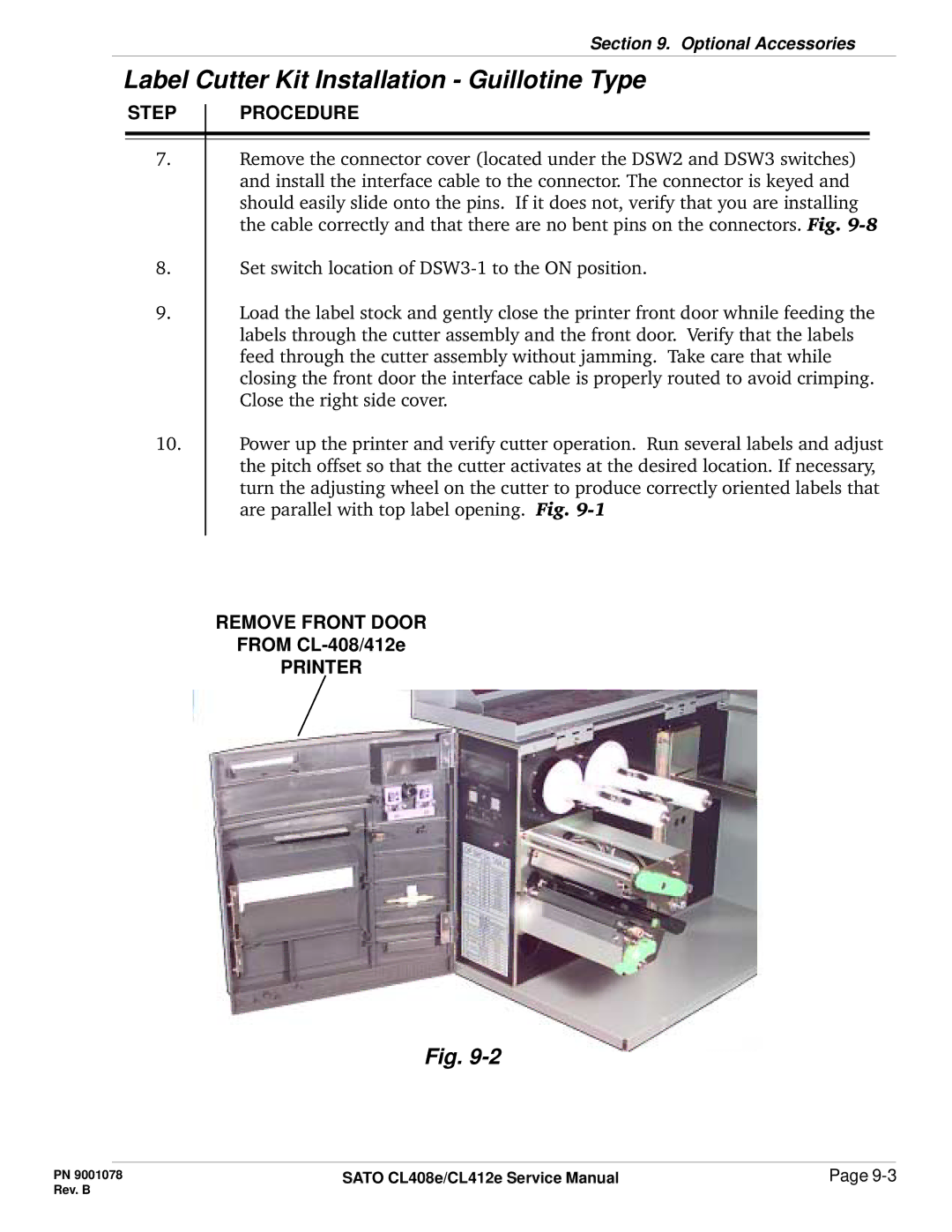
9.Load the label stock and gently close the printer front door whnile feeding the labels through the cutter assembly and the front door. Verify that the labels feed through the cutter assembly without jamming. Take care that while closing the front door the interface cable is properly routed to avoid crimping. Close the right side cover.
10.Power up the printer and verify cutter operation. Run several labels and adjust the pitch offset so that the cutter activates at the desired location. If necessary, turn the adjusting wheel on the cutter to produce correctly oriented labels that are parallel with top label opening. Fig.
REMOVE FRONT DOOR
FROM
PRINTER
Fig.
PN 9001078 | SATO CL408e/CL412e Service Manual | Page |
Rev. B |
|
|