Section 9. Optional Accessories
Label Dispenser Installation
STEP PROCEDURE
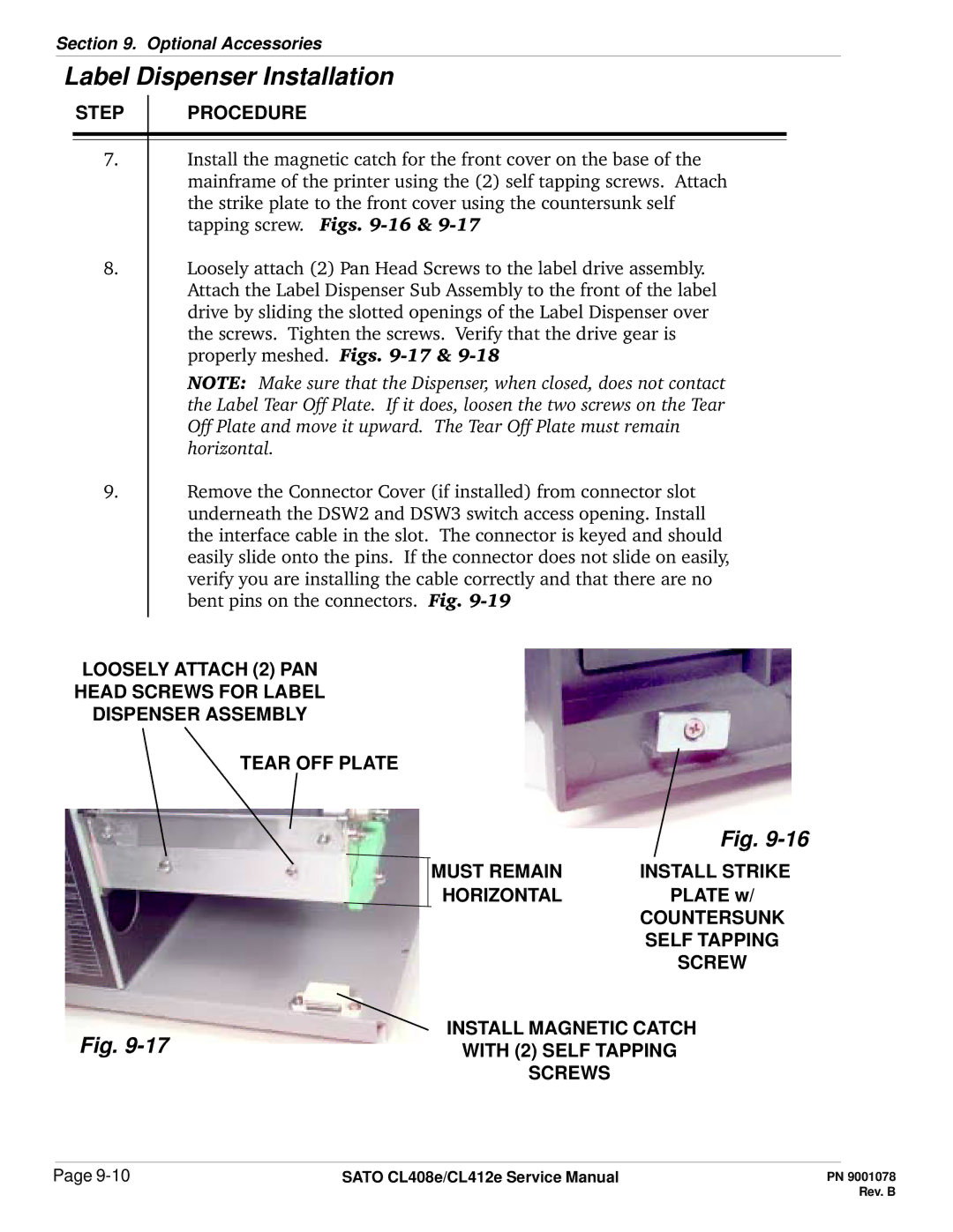
7.Install the magnetic catch for the front cover on the base of the mainframe of the printer using the (2) self tapping screws. Attach the strike plate to the front cover using the countersunk self tapping screw. Figs.
8.Loosely attach (2) Pan Head Screws to the label drive assembly. Attach the Label Dispenser Sub Assembly to the front of the label drive by sliding the slotted openings of the Label Dispenser over the screws. Tighten the screws. Verify that the drive gear is properly meshed. Figs.
NOTE: Make sure that the Dispenser, when closed, does not contact the Label Tear Off Plate. If it does, loosen the two screws on the Tear Off Plate and move it upward. The Tear Off Plate must remain horizontal.
9.Remove the Connector Cover (if installed) from connector slot underneath the DSW2 and DSW3 switch access opening. Install the interface cable in the slot. The connector is keyed and should easily slide onto the pins. If the connector does not slide on easily, verify you are installing the cable correctly and that there are no bent pins on the connectors. Fig.
LOOSELY ATTACH (2) PAN
HEAD SCREWS FOR LABEL
DISPENSER ASSEMBLY
TEAR OFF PLATE
|
| Fig. |
| MUST REMAIN | INSTALL STRIKE |
| HORIZONTAL | PLATE w/ |
|
| COUNTERSUNK |
|
| SELF TAPPING |
|
| SCREW |
Fig. | INSTALL MAGNETIC CATCH | |
WITH (2) SELF TAPPING | ||
SCREWS
Page | SATO CL408e/CL412e Service Manual |