Section 9. Optional Accessories
Label Dispenser Installation
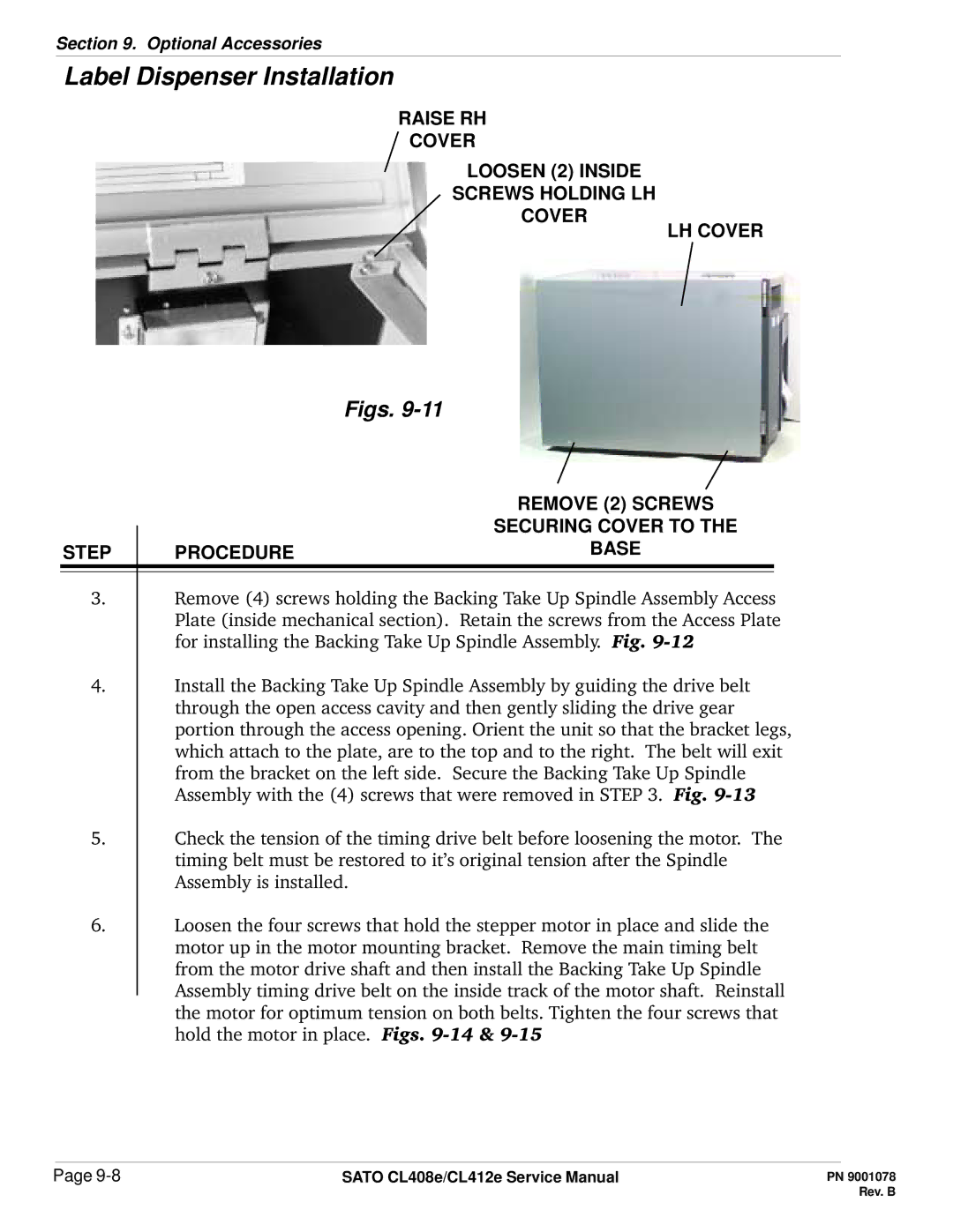
RAISE RH
COVER
LOOSEN (2) INSIDE
SCREWS HOLDING LH
COVER
LH COVER
Figs. 9-11
|
| REMOVE (2) SCREWS |
|
| SECURING COVER TO THE |
STEP | PROCEDURE | BASE |
3.Remove (4) screws holding the Backing Take Up Spindle Assembly Access Plate (inside mechanical section). Retain the screws from the Access Plate for installing the Backing Take Up Spindle Assembly. Fig.
4.Install the Backing Take Up Spindle Assembly by guiding the drive belt through the open access cavity and then gently sliding the drive gear portion through the access opening. Orient the unit so that the bracket legs, which attach to the plate, are to the top and to the right. The belt will exit from the bracket on the left side. Secure the Backing Take Up Spindle Assembly with the (4) screws that were removed in STEP 3. Fig.
5.Check the tension of the timing drive belt before loosening the motor. The timing belt must be restored to it’s original tension after the Spindle Assembly is installed.
6.Loosen the four screws that hold the stepper motor in place and slide the motor up in the motor mounting bracket. Remove the main timing belt from the motor drive shaft and then install the Backing Take Up Spindle Assembly timing drive belt on the inside track of the motor shaft. Reinstall the motor for optimum tension on both belts. Tighten the four screws that hold the motor in place. Figs.
Page | SATO CL408e/CL412e Service Manual |