Section 4. Electric Checks and Adjustments
4.9b Ribbon Sensor Voltage Checking
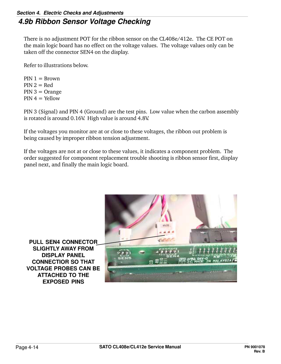
There is no adjustment POT for the ribbon sensor on the CL408e/412e. The CE POT on the main logic board has no effect on the voltage values. The voltage values only can be taken off the connector SEN4 on the display.
Refer to illustrations below.
PIN 1 = Brown
PIN 2 = Red
PIN 3 = Orange
PIN 4 = Yellow
PIN 3 (Signal) and PIN 4 (Ground) are the test pins. Low value when the carbon assembly is rotated is around 0.16V High value is around 4.8V
If the voltages you monitor are at or close to these voltages, the ribbon out problem is being caused by improper ribbon tension adjustment.
If the voltages are not at or close to these values, it indicates a component problem. The order suggested for component replacement trouble shooting is ribbon sensor first, display panel next, and finally the main logic board.
PULL SEN4 CONNECTOR
SLIGHTLY AWAY FROM
DISPLAY PANEL
CONNECTIOR SO THAT
VOLTAGE PROBES CAN BE
ATTACHED TO THE
EXPOSED PINS
Page | SATO CL408e/CL412e Service Manual |