Section 9. Optional Accessories
Label Dispenser Installation
STEP | PROCEDURE |
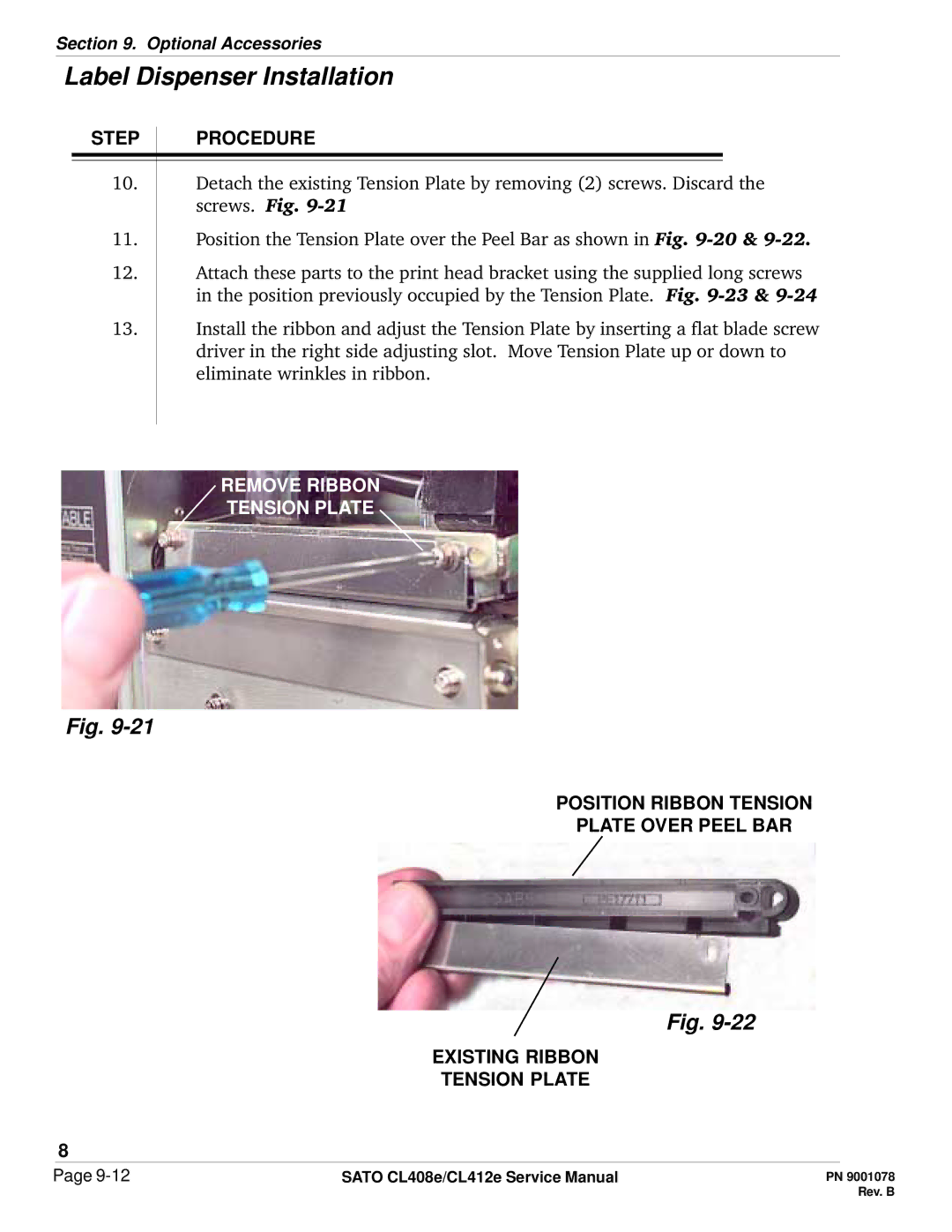
10.Detach the existing Tension Plate by removing (2) screws. Discard the screws. Fig.
11.Position the Tension Plate over the Peel Bar as shown in Fig.
12.Attach these parts to the print head bracket using the supplied long screws in the position previously occupied by the Tension Plate. Fig.
13.Install the ribbon and adjust the Tension Plate by inserting a flat blade screw driver in the right side adjusting slot. Move Tension Plate up or down to eliminate wrinkles in ribbon.
REMOVE RIBBON
TENSION PLATE
Fig.
POSITION RIBBON TENSION
PLATE OVER PEEL BAR
Fig.
EXISTING RIBBON
TENSION PLATE
8
Page | SATO CL408e/CL412e Service Manual |