Section 4. Electric Checks and Adjustments
4.4 Potentiometer Assignments & Adjustments
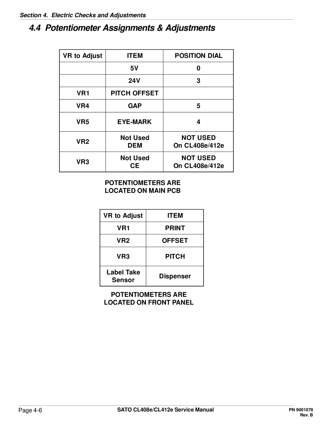
VR to Adjust | ITEM | POSITION DIAL | |
|
|
| |
| 5V | 0 | |
|
|
| |
| 24V | 3 | |
|
|
| |
VR1 | PITCH OFFSET |
| |
|
|
| |
VR4 | GAP | 5 | |
|
|
| |
VR5 | 4 | ||
|
|
| |
VR2 | Not Used | NOT USED | |
DEM | On CL408e/412e | ||
| |||
|
|
| |
VR3 | Not Used | NOT USED | |
CE | On CL408e/412e | ||
| |||
|
|
|
POTENTIOMETERS ARE
LOCATED ON MAIN PCB
VR to Adjust | ITEM | |
|
| |
VR1 | ||
|
| |
VR2 | OFFSET | |
|
| |
VR3 | PITCH | |
|
| |
Label Take | Dispenser | |
Sensor | ||
| ||
|
|
POTENTIOMETERS ARE
LOCATED ON FRONT PANEL
Page | SATO CL408e/CL412e Service Manual |
