Section 9. Optional Accessories
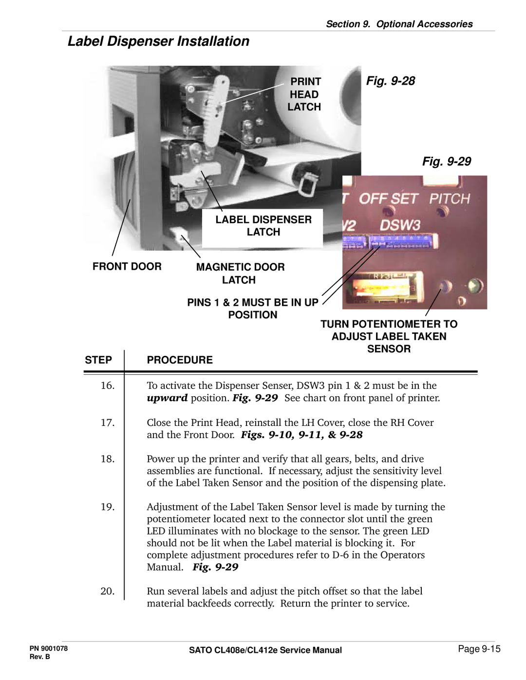
Label Dispenser Installation
Fig. |
HEAD
LATCH
Fig.
|
| LABEL DISPENSER |
|
| LATCH |
FRONT DOOR |
|
|
MAGNETIC DOOR | ||
|
| LATCH |
| PINS 1 & 2 MUST BE IN UP | |
|
| POSITION |
TURN POTENTIOMETER TO
ADJUST LABEL TAKEN
SENSOR
STEP | PROCEDURE |
16.To activate the Dispenser Senser, DSW3 pin 1 & 2 must be in the upward position. Fig.
17.Close the Print Head, reinstall the LH Cover, close the RH Cover and the Front Door. Figs.
18.Power up the printer and verify that all gears, belts, and drive assemblies are functional. If necessary, adjust the sensitivity level of the Label Taken Sensor and the position of the dispensing plate.
19.Adjustment of the Label Taken Sensor level is made by turning the potentiometer located next to the connector slot until the green LED illuminates with no blockage to the sensor. The green LED should not be lit when the Label material is blocking it. For complete adjustment procedures refer to
20.Run several labels and adjust the pitch offset so that the label material backfeeds correctly. Return the printer to service.
PN 9001078 | SATO CL408e/CL412e Service Manual | Page |
Rev. B |
|
|