Section
Configuration | 2 | |
| ||
|
|
|
2.1 Dip Switch Settings
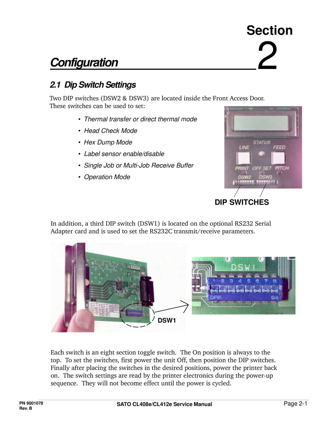
Two DIP switches (DSW2 & DSW3) are located inside the Front Access Door. These switches can be used to set:
•Thermal transfer or direct thermal mode
•Head Check Mode
•Hex Dump Mode
•Label sensor enable/disable
•Single Job or
•Operation Mode
DIP SWITCHES
In addition, a third DIP switch (DSW1) is located on the optional RS232 Serial Adapter card and is used to set the RS232C transmit/receive parameters.
DSW1
Each switch is an eight section toggle switch. The On position is always to the top. To set the switches, first power the unit Off, then position the DIP switches. Finally after placing the switches in the desired positions, power the printer back on. The switch settings are read by the printer electronics during the
PN 9001078 | SATO CL408e/CL412e Service Manual | Page |
Rev. B |
|
|