Section 9. Optional Accessories
Flash Memory Expansion Installation
NOTE: Many of the components on this board are susceptible to damage by static electricity. To avoid damage, do not unpack new circuit boards from
STEP | PROCEDURE |
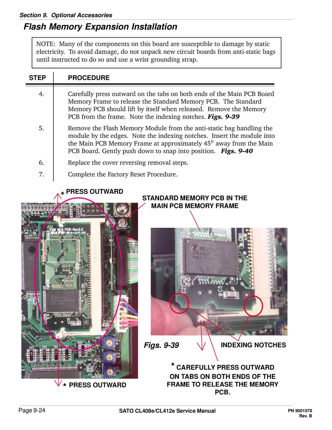
4.Carefully press outward on the tabs on both ends of the Main PCB Board Memory Frame to release the Standard Memory PCB. The Standard Memory PCB should lift by itself when released. Remove the Memory PCB from the frame. Note the indexing notches. Figs.
5.Remove the Flash Memory Module from the
module by the edges. Note the indexing notches. Insert the module into the Main PCB Memory Frame at approximately 450 away from the Main PCB Board. Gently push down to snap into position. Figs.
6.Replace the cover reversing removal steps.
7.Complete the Factory Reset Procedure.
* PRESS OUTWARD | STANDARD MEMORY PCB IN THE |
| MAIN PCB MEMORY FRAME |
Figs. | INDEXING NOTCHES |
* CAREFULLY PRESS OUTWARD
ON TABS ON BOTH ENDS OF THE
* PRESS OUTWARDFRAME TO RELEASE THE MEMORY PCB.
Page | SATO CL408e/CL412e Service Manual |