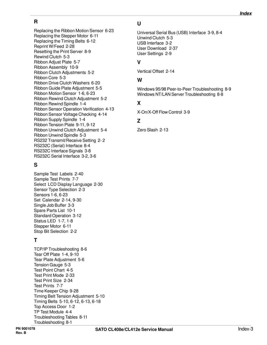
Index
| R |
| U |
|
|
|
|
|
|
| |
| Replacing the Ribbon Motion Sensor | Universal Serial Bus (USB) Interface |
|
| |
| Replacing the Stepper Motor |
|
| ||
| Unwind Clutch |
|
| ||
| Replacing the Timing Belts |
|
| ||
| USB Interface |
|
| ||
| Reprint W/Feed |
|
| ||
| User Download |
|
| ||
| Resetting the Print Server |
|
| ||
| User Settings |
|
| ||
| Rewind Clutch |
|
|
| |
|
| V |
|
| |
| Ribbon Adjust Plate |
|
| ||
| Ribbon Assembly | Vertical Offset |
|
| |
| Ribbon Clutch Adjustments |
|
| ||
| Ribbon Core |
| W |
|
|
| Ribbon Drive Clutch Washers |
|
| ||
|
|
|
| ||
| Ribbon Guide Plate Adjustment | Windows 95/98 |
|
| |
| Ribbon Motion Sensor | Windows NT/LAN Server Troubleshooting |
|
| |
| Ribbon Rewind Clutch Adjustment | X |
|
| |
| Ribbon Rewind Spindle |
|
| ||
| Ribbon Sensor Operation Verification |
|
| ||
| Ribbon Sensor Voltage Checking |
|
| ||
|
|
|
| ||
| Ribbon Supply Spindle | Z |
|
| |
| Ribbon Tension Plate |
|
|
| |
| Ribbon Unwind Clutch Adjustment | Zero Slash |
|
| |
| Ribbon Unwind Spindle |
|
|
| |
| RS232 Transmit/Receive Setting 2- 2 |
|
|
| |
| RS232C (Serial) Interface |
|
|
| |
| RS232C Interface Signals |
|
|
| |
| RS232C Serial Interface |
|
|
| |
| S |
|
|
|
|
| Sample Test Labels |
|
|
| |
| Sample Test Prints |
|
|
| |
| Select LCD Display Language |
|
|
| |
| Sensor Type Selection |
|
|
| |
| Sensors |
|
|
|
|
| Set Calendar |
|
|
| |
| Single Job Buffer |
|
|
| |
| Spare Parts List |
|
|
| |
| Standard Operation |
|
|
| |
| Status LED |
|
|
| |
| Stepper Motor |
|
|
| |
| Stop Bit Selection |
|
|
| |
| T |
|
|
|
|
| TCP/IP Troubleshooting |
|
|
| |
| Tear Off Plate |
|
|
| |
| Tear Plate Adjustment |
|
|
| |
| Tension Gauge |
|
|
| |
| Test Point Chart |
|
|
| |
| Test Print Mode |
|
|
| |
| Test Print Size |
|
|
| |
| Test Prints |
|
|
|
|
| Time Keeper Chip |
|
|
| |
| Timing Belt Tension Adjustment |
|
|
| |
| Timing Belts |
|
|
| |
| Top Access Door |
|
|
| |
| TP Test Module |
|
|
| |
| Troubleshooting Tables |
|
|
| |
| Troubleshooting |
|
|
| |
|
|
|
|
| |
PN 9001078 | SATO CL408e/CL412e Service Manual |
| |||
Rev. B |
|
|
|
| |
