Commissioning (software) 4.6 Using
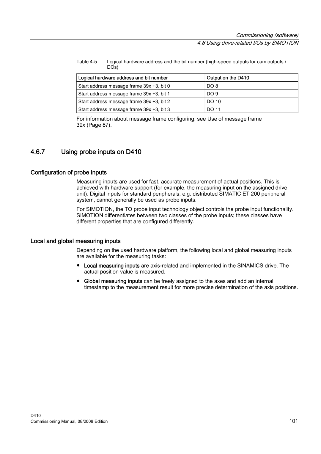
Table
Logical hardware address and bit number | Output on the D410 |
Start address message frame 39x +3, bit 0 | DO 8 |
Start address message frame 39x +3, bit 1 | DO 9 |
Start address message frame 39x +3, bit 2 | DO 10 |
Start address message frame 39x +3, bit 3 | DO 11 |
For information about message frame configuring, see Use of message frame 39x (Page 87).
4.6.7Using probe inputs on D410
Configuration of probe inputs
Measuring inputs are used for fast, accurate measurement of actual positions. This is achieved with hardware support (for example, the measuring input on the assigned drive unit). Digital inputs for standard peripherals, e.g. distributed SIMATIC ET 200 peripheral system, cannot generally be used as probe inputs.
For SIMOTION, the TO probe input technology object controls the probe input functionality. SIMOTION differentiates between two classes of the probe inputs; these classes have different properties that are configured differently.
Local and global measuring inputs
Depending on the used hardware platform, the following local and global measuring inputs are available for the measuring tasks:
●Local measuring inputs are
●Global measuring inputs can be freely assigned to the axes and add an internal timestamp to the measurement result for more precise determination of the axis positions.
D410 | 101 |
Commissioning Manual, 08/2008 Edition |