Commissioning (software) 4.6 Using
Configuring of local measuring inputs on the D410
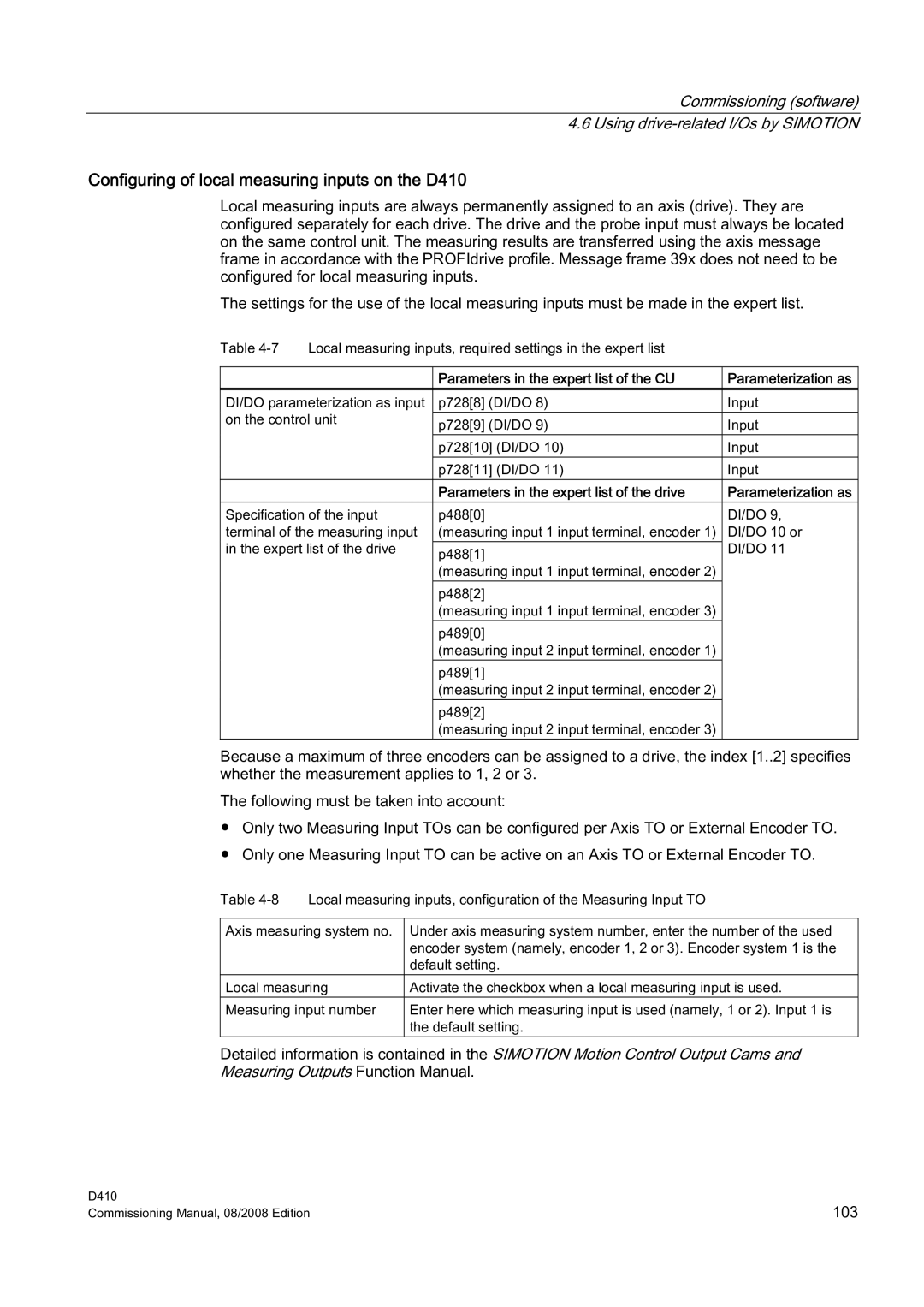
Local measuring inputs are always permanently assigned to an axis (drive). They are configured separately for each drive. The drive and the probe input must always be located on the same control unit. The measuring results are transferred using the axis message frame in accordance with the PROFIdrive profile. Message frame 39x does not need to be configured for local measuring inputs.
The settings for the use of the local measuring inputs must be made in the expert list.
Table | Local measuring inputs, required settings in the expert list |
| |
|
|
|
|
|
| Parameters in the expert list of the CU | Parameterization as |
DI/DO parameterization as input | p728[8] (DI/DO 8) | Input | |
on the control unit | p728[9] (DI/DO 9) | Input | |
|
| ||
|
| p728[10] (DI/DO 10) | Input |
|
| p728[11] (DI/DO 11) | Input |
|
| Parameters in the expert list of the drive | Parameterization as |
Specification of the input | p488[0] | DI/DO 9, | |
terminal of the measuring input | (measuring input 1 input terminal, encoder 1) | DI/DO 10 or | |
in the expert list of the drive | p488[1] | DI/DO 11 | |
|
| (measuring input 1 input terminal, encoder 2) |
|
|
| p488[2] |
|
|
| (measuring input 1 input terminal, encoder 3) |
|
|
| p489[0] |
|
|
| (measuring input 2 input terminal, encoder 1) |
|
|
| p489[1] |
|
|
| (measuring input 2 input terminal, encoder 2) |
|
|
| p489[2] |
|
|
| (measuring input 2 input terminal, encoder 3) |
|
Because a maximum of three encoders can be assigned to a drive, the index [1..2] specifies whether the measurement applies to 1, 2 or 3.
The following must be taken into account:
●Only two Measuring Input TOs can be configured per Axis TO or External Encoder TO.
●Only one Measuring Input TO can be active on an Axis TO or External Encoder TO.
Table
Axis measuring system no. | Under axis measuring system number, enter the number of the used |
| encoder system (namely, encoder 1, 2 or 3). Encoder system 1 is the |
| default setting. |
Local measuring | Activate the checkbox when a local measuring input is used. |
Measuring input number | Enter here which measuring input is used (namely, 1 or 2). Input 1 is |
| the default setting. |
Detailed information is contained in the SIMOTION Motion Control Output Cams and Measuring Outputs Function Manual.
D410 | 103 |
Commissioning Manual, 08/2008 Edition |
