Commissioning (software)
4.6 Using
Configuring of global measuring inputs on the D410
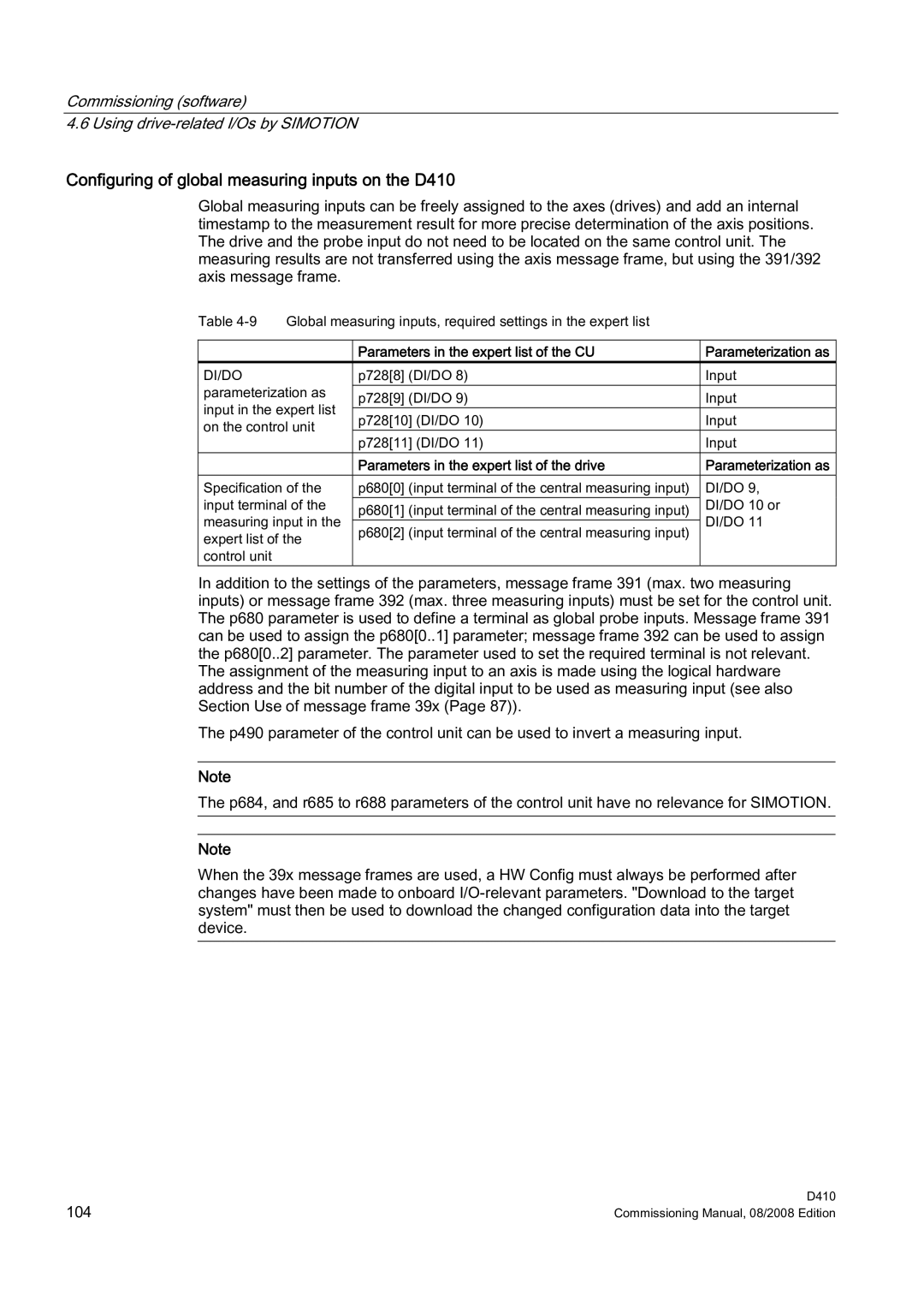
Global measuring inputs can be freely assigned to the axes (drives) and add an internal timestamp to the measurement result for more precise determination of the axis positions. The drive and the probe input do not need to be located on the same control unit. The measuring results are not transferred using the axis message frame, but using the 391/392 axis message frame.
Table | Global measuring inputs, required settings in the expert list |
| ||
|
|
|
| |
|
| Parameters in the expert list of the CU | Parameterization as | |
DI/DO |
| p728[8] (DI/DO 8) | Input | |
parameterization as | p728[9] (DI/DO 9) | Input | ||
input in the expert list | ||||
p728[10] (DI/DO 10) | Input | |||
on the control unit | ||||
p728[11] (DI/DO 11) | Input | |||
|
| |||
|
| Parameters in the expert list of the drive | Parameterization as | |
Specification of the | p680[0] (input terminal of the central measuring input) | DI/DO 9, | ||
input terminal of the | p680[1] (input terminal of the central measuring input) | DI/DO 10 or | ||
measuring input in the | DI/DO 11 | |||
p680[2] (input terminal of the central measuring input) | ||||
expert list of the |
| |||
|
| |||
control unit |
|
|
| |
In addition to the settings of the parameters, message frame 391 (max. two measuring inputs) or message frame 392 (max. three measuring inputs) must be set for the control unit. The p680 parameter is used to define a terminal as global probe inputs. Message frame 391 can be used to assign the p680[0..1] parameter; message frame 392 can be used to assign the p680[0..2] parameter. The parameter used to set the required terminal is not relevant. The assignment of the measuring input to an axis is made using the logical hardware address and the bit number of the digital input to be used as measuring input (see also Section Use of message frame 39x (Page 87)).
The p490 parameter of the control unit can be used to invert a measuring input.
Note
The p684, and r685 to r688 parameters of the control unit have no relevance for SIMOTION.
Note
When the 39x message frames are used, a HW Config must always be performed after changes have been made to onboard
104 | D410 |
Commissioning Manual, 08/2008 Edition |
