Serial NO. DK8 & DK16
Copyright Toshiba America Information SYSTEMS, INC
Page
Toshiba System Practices
INSTALLATION-INTRODUCTION
Digital KEY Telephone Systems
INSTALLATION-INTRODUCTION -016-201 November
March
Section
Paragraph
Table of Contents
Subject
Purpose
INSTALLATION-INTRODUCTION
Organization
Reference Documentation
INSTALLATION-INTRODUCTION
INSTALLATION-INTRODUCTION
INSTALLATION-INTRODUCTION
Use of Notes, Important Notes, Cautions, and Warnings
Page
Chapter TWO Site Requirements
DK8 Base KEY Service Unit and Hpfb Minimum Clearance
INSTALLATION-SITE Requirements
DK16 Combined Base and Expansion KEY Service Unit
General
Input Power Requirements
Site Considerations
Clearance and Location Requirements
Third Wire Ground Test
Electrical/Environmental Requirements and Characteristics
Grounding Requirements
DK16 Base and Expansion Unit Clearance
KSU Grounding Diagram
Summary of ELECTRICAL/ENVIRONMENTAL Characteristics
General
Alternate or Additional Ground
Digital KEY Telephone Systems
Toshiba System Practices
Page
Title
Worksheets
INSTALLATION-CONFIGURATION -816-203 March
System Capacity
Introduction
DK8 CO LINE/STATION Configuration Guide
Supports Connector Type Standard Optional
DK8 KEY Service Unit Components
DTMF/ABR
DK16 Base KEY Service Unit Components
Telephone Circuit Port Types
Station Considerations
Digital Telephone Circuit Connections
Strata DK8 Station Apparatus Overview
PIOU/PIOUS Interface Option DK16 only
Expansion Unit Interface Options
Piou Pious
Capacity Unit Combined Capacity
Strata DK16 Station Apparatus Overview
Standard Telephone Circuit Options
Maximum of two Qcdu PCBs may be installed in the Strata DK8
Configuration Examples
Telephone Upgrades
Strata DK16 Example 1 Bank
Configuration Worksheets
Strata DK16 Example 2 Office/Ware- house
Digital Ports Circuits
DK8 Worksheet 1, Station and CO Line Totals
Device Quantity Ports/Per Ports Used
Standard Ports Circuits
KSU Optional Unit Station and Line PCBs
KSU Interfaces built-in
Base Unit Peripherals
DK8 Worksheet 3, Peripherals and Upgrades
DDCB/MDFB Door Phone Total DDCBs Total MDFBs
Miscellaneous Peripherals Hesb Amplifier/Speaker Total
Electronic Ports Circuits
DK16 Worksheet 1, Station and CO Line Totals
Expansion Unit Station and line PCBs
Base Unit Interfaces/PCBs
Expansion Unit Peripheral PCB
DK16 Worksheet 3, Peripherals and Upgrades
Miscellaneous Peripherals Dpft Yes or No
HVSU2 or Combined HVSU/HVSI Total
Eocu Yes or No
Mdfb Door Phone Total
Equipment Type Power Used Ports Used Quantity
DK16 Worksheet 4, System Power Check
Total Power Used
Power Criteria Power Supplied Total Power Used
Page
Chapter Four DK8 KSU and PCB Installation
Page
Part
INSTALLATION-DK8 KSU & PCB
Subject
Table of Contents
10.40 Qcnu Programming Overview
Option Interface Unit Qsmu
KEY Service Unit Mounting
Part I. KSU Installation General
DK8 KEY Service Unit Wall Mount Method
Mounting Surface Considerations
DK8 Dimensions and Screw Locations
INSTALLATION-DK8 KSU & PCB -816-204 March
DK8 Side View Dimension and PLUG/JACK Locations
Left Side View Right Side View
Installing the Reserve Power Battery and Charger Hpfb Figure
Section March Mounting the Key Service Unit
DK8 Power Failure Emergency Transfer Option
Power Supply Removal Replacement
Power Supply Removal Figure
Power Supply Replacement Figure
AC Power Cord
Left Side View DK8 Cabling Diagram Right Side View
DK8 Base Unit Jacks and Connectors
Section March
PCB Installation Considerations
Part II. Printed Circuit Board Installation General
CO LINE/DIGITAL Telephone Interface Unit Qcdu
DK8 Printed Circuit Board Installation
Qcdu Installation Procedure
Qcdu Configuration
Modular Jack Cover Removal and Storage
Qcdu Wiring
Dtmf RECEIVER/ABR Tone Detector Unit Qrcu
Standard Telephone Interface Unit Qstu
Qrcu Installation Procedure
Qrcu Configuration
Qsts Factory Installed Qstu
Qsts
Conference Circuits Qcnu
Qrcu Interface Connectors
Option Interface Unit Qsmu
Qcnu Interface Connectors
Right
BUILT-IN CO LINE, Digital TELE- PHONE, and Other Circuits
Page
Chapter Five DK16 KSU and PCB Installation
INSTALLATION-INTRODUCTION -816-205 March
DK16 KSU Installation General DK KEY Service Unit Mounting
INSTALLATION-DK16 KSU & PCB
DK16 Power Failure Emergency Transfer Option
Kcou Removal and Replacement
STANDARD/ELECTRONIC Telephone Interface Unit Pesu
CO Line Unit Pcou
Iii
Table List Subject
Important Initial Installation Notes
Drill holes on these marks
Mounting the Base Key Service Unit
DK16 Base KEY Service Unit Wall Mounting Methods
DK16 Base KEY Service Unit Exterior
Method
INSTALLATION-DK16 KSU & PCB -816-205 March
DK16 Base KEY Service Unit Interior
Mounting the Expansion Key Service Unit
DK16 Base KEY Service Unit Wiring Connections
Connecting the DK16 Expansion Unit to the DK16 Base Unit
Mounting the DK16 Expansion Unit
DK16 Expansion Unit Interior
DK16 Expansion Unit Wiring Connections
Important Note
Reserve Power/Power Failure Options
Power Supply Replacement
Power Supply Removal
Power Supply KPSU16
DK16 PCB Installation Considerations
Part II. DK16 Printed Circuit Board Installation General
INSTALLATION-DK 16 KSU & PCB
10 DK16 Base Unit PCBs
PCB Installation/Power Supply Consider- ations
Kstu Options and Connectors
Kstu Configuration
Kstu Installation Procedure
Kstu Controls and Interface Connectors
Kstu Wiring
Digital Telephone Interface Unit Pdku
Type of Component Description
Pdku Interface Connection
Hardware Configuration
Pdku Hardware Options
Internal option
Electronic Telephone Interface Unit Peku
Peku Controls and Interface Connectors
Peku Installation Procedure
Peku Controls and Interface Connectors
CONTROL/INDICATOR
Peku Wiring
OFF-HOOK Call Announce Unit Eocu Interface Connectors
Standard Telephone Interface Unit Pstu
Peku Programming Overview
Pstu Installation Procedure
INSTALLATION-DK 16 KSU & PCB -816-205 March
STANDARD/ELECTRONIC TELE- Phone Interface Unit Pesu
Pstu Wiring
Pstu Programming Overview
Pesu PCB Option Location and Identification
Connector Figure
Pesu Controls and Interface Connectors
Section March Program
CO Line Unit Pcou
Pcou CONTROLS, INDICATORS, and Interface Connectors
Programs 45 ~
Program 42-0
Programs 50 ~
Programs 81 ~
Option Interface Unit Piou and Pious
Piou CONTROLS, INDICATORS, and Interface Connectors
SW2
Piou Controls and Interface Connectors
Pious
INSTALLATION-DK 16 KSU & PCB Section
CO LINE/DIGITAL Telephone Interface Unit Kcdu
Pious Controls and Interface Connectors
Kcdu INDICATORS, OPTIONS, and Connectors
Remote Maintenance Modem Unit Imdu Iinterface Connectors
14.10 K4RCU Configuration
Kcdu CONTROLS, INDICATORS, and Connectors
14.20 K4RCU Installation Procedure
Dtmf RECEIVER/ABR Tone Detector Unit K4RCU
BUILT-IN CO Line and Digital Telephone Circuits
Section March 14.30 K4RCU Wiring
K4RCU PCB
14.40 K4RCU Programming Overview
Section March Kcou Replacement
Kcou Removal and Replacement
Kcou PCB
Krcu
DK16 Base Unit Power Failure Transfer PFT Circuit Diagram
17 DK16 Power Failure Emergency Transfer Option
17.11 DK16 Power Failure Emergency Trans- fer Test
Chapter SIX Station Apparatus Installation
INSTALLATION-STATION Apparatus Section
Telephone Installation
INSTALLATION-STATION Apparatus
Digital Telephone Upgrades
Installation
Figure List Title
Overview
Telephone Installation
Purpose
See -816-208for secondary pro- tector information
Handset Hanger
Removing the Telephone Base
Wall Mounting Base Rotation
Simultaneous Voice and Data Upgrade PDIU-DI2 and PDIU-DI
Digital Telephone Upgrades
Programs 20
PDIU-DI Installation Into 1000-SERIES Digital Telephone
PDIU-DI2 Installation Into 2000-SERIES Digital Telephone
PDIU-DI PCB
Section March Off-hook Call Announce Upgrade Dvsu
Dvsu Installation for Digital Telephones
Locations Strap and Connector Locations
DKT2010-H Strap and Connector
Series Digital Telephone Strap and Connection Locations
HESC-65A Cabling
Hheu Installation for Digital Telephone
Bell-even if a headset is also installed on the Hheu
External Power Straps
90 DKT2000 Add-On-Module Installation
HVSU2 Installation for Electronic Telephones
Electronic Telephone PCB Connections
HVSI/HVSU Installation for Electronic Telephones
Hheu Installation for Electronic Telephones
Microphone/Speaker Threshold Speak- erphones only
Direct Station Selection CONSOLE/SYSTEM Connection
Ddss Programming Overview
Door PHONE/LOCK Control Unit and Door Phone Installation
Hdss Programming Overview
Ddcb and Mdfb Cabling
Door Phone Ddcb Installation
ADD-ON Module Installation
Door Phone Mdfb Installation
Door Phone/Lock Programming Consid- erations
Night Transfer All Call
Chapter Seven Peripheral Installation
Page
External page Options
External Speaker Unit Hesb Options
PRINTER/CALL Accounting Device Options
Voice Mail Options
INSTALLATION-PERIPHERALS
Section March Relay Contact Specifications
MOH Source Specifications
MUSIC-ON-HOLD/BACKGROUND Music Options
10 DK8 and DK16 Music-on-Hold MOH Option
DK8 KSU or DK16 Base KEY Service Unit Twisted Pair VR1
Background Music BGM Options
Relay Control Options
DK8 and DK16 Music Source Configuration B
DK8 and DK16 Music Source Configuration a
DK16 Music Source Configuration C
Voltage
10 DK8 KSU and DK16 Base Unit Relay
Current
20 DK16 Expansion Unit Piou and Pious Relays
Ddcb Installation
DK16 Piou Relay Control Functional Wiring Diagram
Door Lock Assignments Guide
DK16 Pious Relay Control Functional Wiring Diagram
See Program 77-1, LED 07
See Figure
DK8 and DK16 Door Lock Control Option Ddcb
Ddcb to DK8 KSU Wiring Chart Port no DK8 Amphenol KSU Jack
System Hardware Requirements
External Speaker Unit Hesb Options
INSTALLATION-PERIPHERALS
See Section
INSTALLATION-PERIPHERALS
DK16 HESB/ELECTRONIC Telephone with Loud Ringing Bell Wiring
INSTALLATION-PERIPHERALS
DK8 and DK16 HESB/AMPLIFIED Speaker Wiring
Power Converter
DK8 and DK16 HESB/TALKBACK Amplified Speaker Wiring
Hesb Wall Mounting
External page Options
ONE Wall
Mounting
Must Turned Off
DK8 and DK16 page and Separate BGM Using Same Amplifier
Program Zone
DK16 Piou ZONE, PAGE/BGM/NIGHT Ring Separate Amplifiers
LED on LED OFF
Button/LED
DK16 Paging with Multiple Amplifiers
INSTALLATION-PERIPHERALS
DK16 Night Ringing Over ALL External page Zones
Printout a
Smdr Printout Examples
Printout B
Printout C
DK8 and DK16 Smdr Printout Examples
Smdr Hardware Requirements
Disconnect Timer
Smdr Programming Considerations
Smdr Printer/Call Accounting Device In- stallation
Device
Basic Connection
CO Line Station Port Numbers Program Number
PIOU/PIOUS Smdr Port Program 97 Data Dump Example
K4RCU or Qrcu allows VM Dtmf dialing
DK8 and DK16 Voice MAIL/AUTO Attendant Block Diagram
INSTALLATION-PERIPHERALS
DK16 Alarm Sensor Installation
DK16 Night Ringing Over External Zone
DK16 Alarm Sensor Block Diagram PIOU/PIOUS
Data Interface Unit Installation
Important Notes
DIP Switch Options
Important Note
PDIU-DS to Modem Installation
Important Note
Program 22/33
Modem Setup Recommendations
Disassembling the PDIU-DS
Assembling the PDIU-DS
DK8 or DK16 Data Installation Example Block Diagram
PDIU-DI Functions Like a DCE
Toshiba Laptop or IBM AT-TYPE Personal Computer DTE
DB25 PIN Designations
Name PIN # DCD DTR DSR RTS CTS
Rear view of modem DB25 connector
Connection Example
Type RJ45 to DB25 Male Adapter
Type RJ45 to DB9 Female Adapter
Type RJ45 to DB25 Female Adapter
RJ45 Cross Pinning
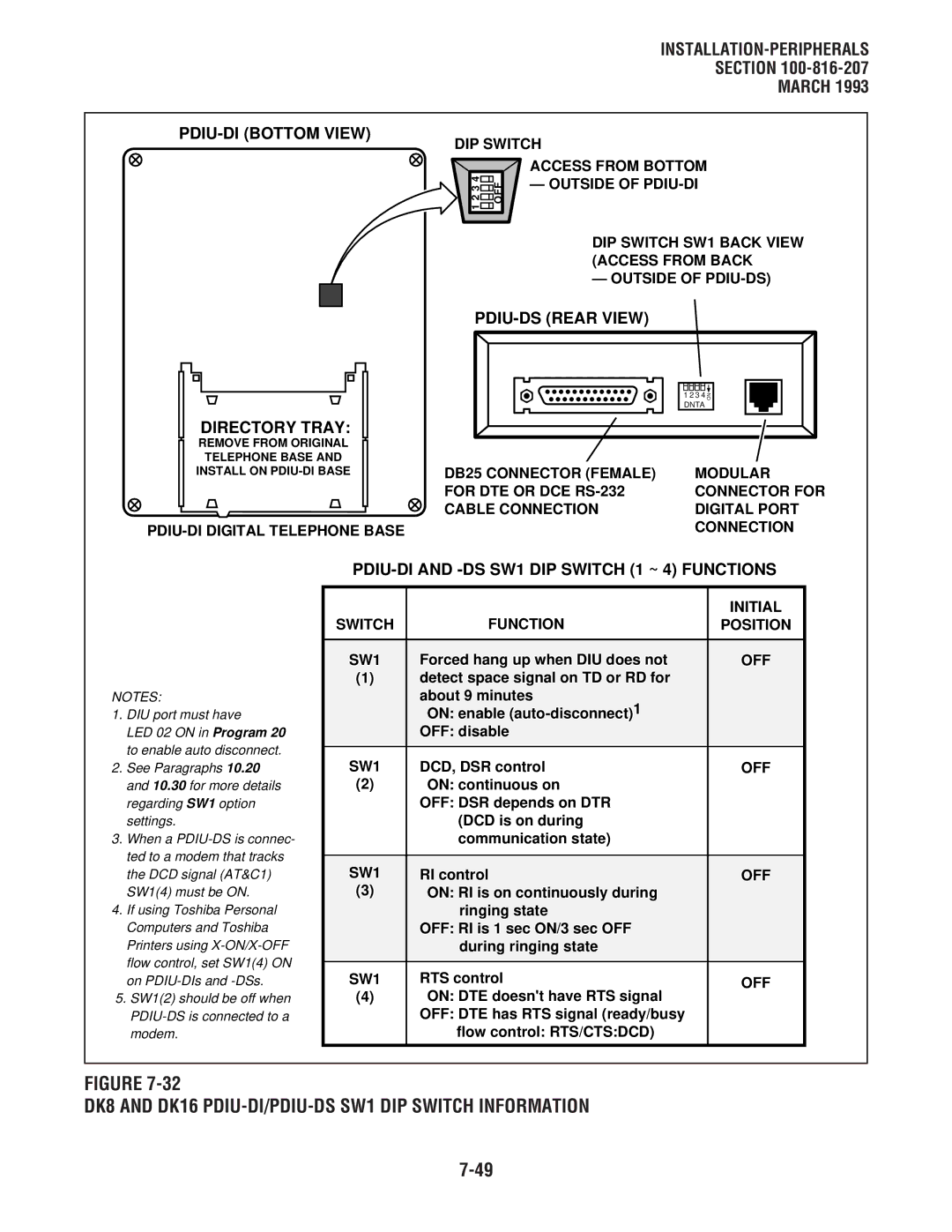
PDIU-DS Rear View
PDIU-DS Front View
CTS
DSR DCD
DIP Switch
DK8 and DK16 PDIU-DI/PDIU-DS SW1 DIP Switch Information
Function Initial Switch
PDIU-DI Digital Telephone Base
Bottom Panel
DK8 and DK16 PDIU-DS DISASSEMBLY/ASSEMBLY Diagram
PC-to-PC Test Call Using AT Commands see Figure
DK8 and DK16 PC to PC Test Call Using AT Commands
Laptop PC
DKT/PDIU-DI Strata DK8 or DK16 MDF Digital
PC to Printer Test Call Using Manual Dialing see Figure
DK8 and DK16 PC to Printer Test Call Using Manual Dialing
Strata DK8 or DK16 MDF Digital
Strata DK8 or DK16 Qstu or Kstu Line
Internal
Public
Telephone Line
Laptop PC MDF
MDF Internal Modem
External Modem Laptop
PC Auto Dial Voice Call Test see Figure
Data Release button,
DK8 and DK16 PC Auto Dial Voice Call Test
11 DK16 TWO-CO Line External Amplified Conference
Standard Telephone
Laptop PC MDF DKT/PDIU-DI Strata DK8 or DK16 Digital
All Amplifier Equipment is customer Or dealer
Following steps see Figures 7-39
Amplifier Requirements
Chapter Eight Wiring Diagrams
Page
DK8 MDF Wiring to KSU Amphenol Station and Relay
INSTALLATION-WIRING Diagrams
DK16 MDF WIRING/BASE Unit P5 Amphenol Station and Relay
DK16 MDF Wiring for Digital Telephones Dkts and Digital
Table List Title
Station Wiring Diagrams
Wiring Diagrams
CO Line Wiring Diagrams
Piou and Pious Wiring Diagrams
Station Loop Requirements
Network Requirements
Digital TELEPHONE/DIU/DDSS CONSOLE/ADM/LOOP Limits
INSTALLATION-WIRING Diagrams -816-208 March
Secondary Protector Diagram
Digital or Electronic Telephone Mdfb
CO Line
INSTALLATION-WIRING Diagrams
DK8 MDF Wiring to KSU Amphenol Station and Relay Connections
INSTALLATION-WIRING Diagrams Section
DK8 MDF Wiring to CO Lines KSU and Qcdu
DK8/DK16 MDF Wiring Ddcb and Door Lock Control
DK8 and DK16 CO Line Record
DK8 QSTU/DK16 Kstu STATION/MDF Cross Connect Record
MDF Pair CO Line Base Unit Numbers KCDU/PCOU RJ11C/RJ14C
Types of modular adaptors
DK8 Qsmu TTY/SMDR Wiring
Voltage levels
DK16 MDF WIRING/CO Lines to Base Unit
INSTALLATION-WIRING Diagrams
DIU
MDF Block no Slot no
Circuit OCA T1 OT OCA R1 or
DK16 MDF WIRING/ELECTRONIC Telephone to Peku
For electronic telephone
Only not at Peku
DK16 Peku Background Music Connection
DK16 Peku STATION/MDF Cross Connect Record
W1, ring voltage option = 130V P-P = 190V P-P
DK16 MDF WIRING/STANDARD TELEPHONE, Voice Mail to Pstu
DK16 Pstu STATION/MDF Cross Connect Record
To Tip/Ring
DK16 Pesu Circuit Card Wiring Diagram
DK16 Pesu STATION/MDF Cross Connect Record
DK16 MDF WIRING/CO Lines to Pcou
CO Line Cabling
DK16 MDF WIRING/CO Lines and Digital Telephones to Kcdu
P5 Amphenol
DK16 MDF WIRING/PIOU Peripherals 25-PAIR
Even Parity
DK16 PIOUS/TTY and Smdr Wiring
Pious
DK16 Pious PAGE/RELAY/ALARM Connections
DK16 Piou SMDR/TTY Options and Wiring
System Programs
DK16 MDF WIRING/AMPLIFIED TWO-CO Line Conference
AC/DC External Power Source Specifications
DK16 External Power for Digital Telephone Connection
Fault Finding Procedures
Page
Chart no
Strata DK Fault Finding
Chart no Voice MAIL/EXTERNAL Auto Attendant
Chart no Station Message Detail Recording
Page
Flowcharts
Fault Classification
Fault Clearing Procedures
Flowchart Symbols
DK8 Hardware Fault Isolation
Fault Identification and Elimination Procedures
Defective Apparatus Returns
Do not
QPSU8 DC Voltage Test
Fault Finding -816-500 March
KPSU16 DC Voltage Test
Station Cable Continuity Check
DK16 Hardware Fault Isolation
Fault Isolation Flow Charts
Table D
Table B Electronic Telephone Cables
Start
Chart no Fault Classification
Start
Chart no Catastrophic Faults
KCDU, Pdku PEKU, Pesu
Chart no Station Dial Tone Faults
Start
Chart no CO Line Dial Tone Faults
Hdss
Chart NO.5 DSS Console Faults DK16 only
Qrcu
Chart NO.6 Voice MAIL/EXTERNAL Auto Attendant VM/AA Faults
Chart NO.7 Station Message Detail Recording Smdr Faults
Chart NO.8 Remote Maintenance Faults
Remote Administration Maintenance Procedures
Remote Administration and Maintenance Procedures Section
Using Remote Administration and Maintenance
Remote Administration & Maintenance Procedures
Table List Paragraph Subject
RM-Q Type 1 Program Procedure Example Programs 10-1, 10-2
RM-J Program 92 Call Forward Backup RAM Initialization RM-K
RM-C
RM-D
RM-AN Program 44 a or B Toll Restriction Traveling Class
RM-BT General Station Access and Button Activation RM-BU
RM-AO
RM-AP
Message Record Sheet
Index
Message Record Sheet
Section Flowchart
Using Remote Administration and Maintenance
Remote Administration and Maintenance Procedures
Hardware Requirements
General Description
DK8 or DK16
DK8 or DK16
DK16
Remote Maintenance Using Imdu Modem DK16 only
TERMINAL/MODEM Installation
Remote Maintenance Option Installation
20 DK8 and DK16 Local Maintenance Terminal Installation
Programming
50 DK16 Imdu On-site Testing
Remote Terminal Operation
Local Terminal Operation
Requirements
Set-up
Remote Operation
Program Mode
Mode Selection
Selecting a Mode
Table RM-C-PROGRAMMING Prompts
Data Dump Mode
CO Line Testing
Test Mode
Data Dump Printout Example
Sample Printout of System Messages
LCD Message Mode
Test Mode Function Diagram
Remote Called Station Message Mode
Remote Calling Station Message Mode
Mode Exit
Speed Dial Mode
Discontinue Operation
Equipment Compatibility
Enter Program Number
Enter the Program Mode
To Initialize All Programs Enter 0 0 * 9
Exit Program
Step Action DISPLAY/PRINTOUT
System Speed DIAL, Speed Dial Memo Initialization
Table RM-F
LCD Character Message Memory Initialization
Table RM-G
Timed Reminders Initialization Step Action DISPLAY/PRINTOUT
Table RM-H
Table RM-I
Digital Telephone Volume Level Initialization
Table RM-J
Call Forward Backup RAM Initialization
Enter the Slot Number
Table RM-K Program Slot Assignments
Enter the PCB Code Number
To Exit Program/Store Data
To Change Level 1 Security Code
To Check Software Version
To Change Level 2 Security Code
Table RM-N Program Physical Port Display
Table RM-M Program Logical Port Display
Enter Access Code number that you wish to change 0 ~
Table RM-P Program Flexible Access Code Numbering
Change the number if required one or two digits
Table RM-Q Type 1 Program Procedure Example
Programs 20, 30, 31, 35, 40, 41, 43, 79, 81 ~
Table RM-R Type 2 Program Procedure Example
Enter Port Number Or Port Range
Enter the Desired Button/LED Number
Table RM-T Program Defining the Message Center
Table RM-S Program System Assignments Basic Timing
Example Port 00, enter 0 0 CR
Press # # CR
P19
Table RM-V Program Modem Pooling
P1 19 ##
P21
P22
Table RM-W Program Data Station Hunting Data Call only
P22 03# NN
P28
Enter New 2- or 3-digit Feature Code
Remote Administration and Maintenance Procedures
P29
Enter Console Number and Buttonstrip Group Number
Table RM-AA Program Station Hunting
Table RM-Z Program Automatic Preference
Enter the Program Number
Table RM-AC Program Fixed Call Forward
P37
Table RM-AD Program Ring Transfer CAMP-ON Recall Time
P37 01#
P37 01# 064
P38
Action DISPLAY/PRINTOUT
P38 00#
P38 00# 31
P39
Table RM-AF Program Flexible Button Assignment
P39 00#
P39 00# 01
Program 42-1 ~
Table RM-AG
Step Action DISPLAY/PRINTOUT
Table RM-AH Program Smdr OUTPUT/ACCOUNT Code Digit Length
P69
Table RM-AI Program Verifiable Account Code Entry
P69 Nnnnnn
P70 002 YZ
P70
P78 13 01 N
P78
P80 01#
P80
P80 01# 1
P93
Table RM-AM Program CO Line Identification
Enter Action Code
Enter Program Number 44 Do not enter a or B
Table RM-AO Program Toll Restriction Dial Plan
Enter the number
Example Code 2, enter To Exit Program/Store Data
P45 01 N
Table RM-AQ
P45 01 N Y
P45 Nnnnn
Toll Restriction Override Code
Table RM-AR
Table RM-AS
Program 46-6 ~
Table RM-AT
Toll Restriction Class Parameters
Table RM-AU
To Delete Exception Office Codes from Table
To Add Exception Office Codes to Table
To Display Exception Office Codes in Table
To Exit Program/Store Data # # CR
Table RM-AX Program LCR Parameters
Table RM-AW Program Station Toll Restriction Classification
To store data, press CR To exit this program, press # # CR
LCR Special Codes
Table RM-AZ
Table RM-BB Program LCR Local Call Plan Number
Table RM-BA Program LCR LDI Plan Number
Exit Program/Store Data
P51
Table RM-BD Program LCR Area Codes
212
Define Area Code Number
Define Route Plan Number
Display Office Codes
To Add 2 or Delete 3 Office Codes
Define Schedule Number
Table RM-BF Program LCR Schedule Assignment
Enter Code Number
Priority Class Assignment
P54
Table RM-BG Program LCR Route Definition
Enter Route Plan Number
Enter Route Definition Number
Enter Modified Digits Table Number
P55
Enter Code
P55 10 05
3 4 P3
Table RM-BI Program LCR Modified DIGITS-ADD
Table RM-BJ Program LCR Modified DIGITS-END
Table RM-BL Program Data Dump
Table RM-BK Program LCR Station Group Assignment
Table RM-BM Speed Dialing Data Dump
To Exit the Dump Mode Enter Q U I T CR
Table RM-BN LCD Messaging Data Dump
To Output Speed Dialing Data
To Exit the Message Mode
Enter the Message Mode
To Add Or Review a Calling Station Message
To Change Previous Message
M97 XXX p
M97
To Add a Message
To Set the Message on the DKT/EKT LCD
To Change the Message M+
To Add Or Review a Called Station Message
To Set Message
To Add the New Message M
To Change or Add a New Called Station Message
To Set the Message
Table RM-BS STATION/CO Line Status Check
Table RM-BU CO Line Test
To Set Up a CO-to-CO Connection
To Verify Station/CO Line Status
To Set Date
Table RM-BV System DATE/DAY/TIME Setting Procedure
TK00 K01 651YYMMDD#
TTK00 K01 652HHMMSS#
Table RM-BW Speed Dial Mode CHANGE/REVIEW
Remote Maintenance Procedures Index
MESG.#