Reference Guide
Copyright License under the clause at Dfars 52.227-7013 APR
Manufacturer’s Declaration
Herstellerbescheinigung
General
Safety Considerations for this Instrument
Product Markings
Mobile Station Test Set Duration of Warranty 1 year
E8285A Cdma
\agilent\e8285\REFGUIDE\MANUAL\frntmt.fb
Declaration of Conformity
Agilent Technologies E8285A Support Contacts
Regional Sales and Service Offices
This Book
Testing
Testing and for analog testing
Technologies E8285A
Documentation Map
Specifications 5968-8839E
Instrument Basic User’s Handbook E2083-90000
Contents
101
100
102
106
104
105
108
144
148
Cmax
Dsat
ESN
Contents
MS FER
Rand
Randu
SID MSB
System ID 418 System Type Call Control
Contents
Description of Keys
Keys are listed in alphabetical order
Agilent Technologies E8285A Front Panel
Answer
Keys
Address
This sets the Test Set’s Gpib address to
See Also
Assign
Average
Programming Average
Output 714MEASAFRDISTNAVERSTAT on
Call/Page
Cancel
EEX
Enter
Ibasic reset
End/Release
Hold
This queries the increment value for the RF Gen Freq field
Increment ÷10, Increment set, Increment
Programming Increment set
Output 714RFGFREQINCRMODE LOG
Increment value from 10 MHz to 1 MHz
Frequency
Programming Increment÷10
Programming Increment ×10
K1 K5, & K1’- K3’
Cannot be changed
Low limit, High limit
Puts the device at address 14 in local mode
Local
Programming Local
Output 714MEASAFRDISTNHLIMSTAT?
Used to display the high and low measurement limit values
Analyzer FM deviation measurement
Deviation measurement
Viation measurement have been exceeded
HLIMitEXCeeded? and LLIMitEXCeeded? commands to detect if a
YES
To Detect If a Measurement Limit Has Been Exceeded. Use
This resets all of the active measurements in the Test Set
Meas reset
Programming Meas reset
Programming Meter
Meter
To Turn the Meter on and OFF
To Set the Number of Intervals on the Meter
To Query the State of the Meter
To Query the Number of Intervals on the Meter
Graph meter high endpoint and low endpoint
Endpoint to 10 watts for the TX power measurement
Meter for the TX power measurement
To Set the Meter High End and Low End Points
To Set the Meter High End and Low End Point Display Units
Graph meter for the TX power measurement to dBm
To Query the Meter High End and Low End Point Display Units
No Ratio W
Power
Preset
On/Off
Print
This recalls the instrument state saved in the file SETUP1
See Also Print Configure Screen on
Recall
Ref set
Programming Ref set
Commands to query a measurement reference point
Set a measurement reference point
Measurement to dBm
Release
This saves the instrument state to a file named SETUP1
Register
Save
Shift
Yes On/Off
To 9, decimal point ., +/-, and a to F
Down-Arrow, Up-Arrow
Symbol Keys
Backspace
E8285A User’s Guide
Units-of-Measure Keys
Front Panel Knobs
Miscellaneous Hardware
Cursor Control Knob
Programmable Front-Panel Keys for Screens
Key Name Screen Displayed Gpib Example
Non-Programmable Front-Panel Keys and Functions
Guidelines for Using Measurement Data Functions
Data Functions Keys
Guidelines for Using Numeric Entry Field Data Functions
User Keys
Description of Connectors
Connectors are listed in alphabetical order
Description of Connectors
Agilent Technologies E8285A Rear Panel
Antenna
Connectors
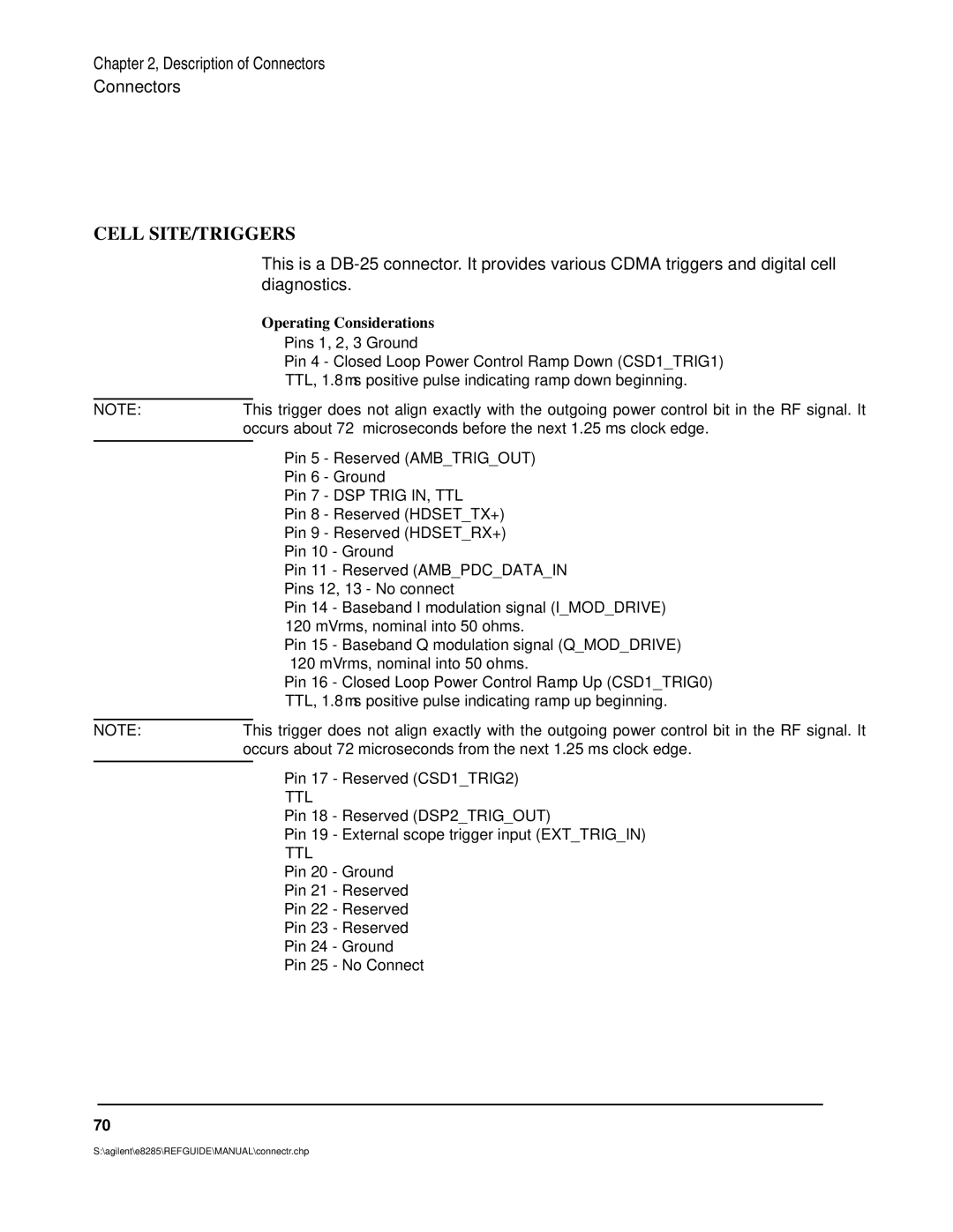
Operating Considerations
Audio in LOW, High
AUD Monitor Output
Audio output is used to output signals from AF Generators 1
Audio OUT
See Also Scope To field description, on
Cell SITE/TRIGGERS
Cdma Clock MUX Output
Composite Video
Even SEC Input
Duplex OUT
See Also Cdma Clock MUX Output field description, on
Gpib
EXT REF Input
See Also Gpib Adrs field description, on
Modulation Input
Pin assignments for this connector are as follows
Paging Channel Logging DCS2
Parallel Port
Protocol Serial
RF IN/OUT
SA Trig Output
Serial Port
Serial Port
16X Chip Output
Traffic Channel Logging DCS1
See Also Cell SITE/TRIGGERS on
MHz Output
See Also EXT REF Input on
Description of Screens
These screens are listed in alphabetical order
Adjacent Channel Power Screen
Adjacent Channel Power Screen
How the Test Set Measures Adjacent Channel Power ACP
AF Analyzer Screen
AF Analyzer Block Diagram on
AF Analyzer Screen
AF Analyzer Block Diagram
AF Analyzer Functional Block Diagram
Call Control Screens
Call Control Screen
Call Control Screens Analog Meas
Analog Meas Screen
Requirements for Using The Analog Meas Screen
How To Program The Analog Meas Screen
Call Control Screens Authentication
Authentication Screen
Call Control Screens Call BIT
Call BIT Screen
Using the Call BIT Screen
General Syntax
Example of Querying a Single Field
Call BIT Screen Signaling Message Names
Example Printout
General Syntax’
Printed Test Set Response Message
Example of Modifying Multiple Fields With One Output
Call Control Screens Call Configure
Call Configure Screen
Call Control Screens Call Data
Call Data Screen
Messages which can be viewed are
Reading the Call Data Screen Message Fields
Aword
Querying a Single Field Example of Querying a Single Field
Querying Multiple Fields With Single OUTPUT/ENTER
Cdma Authentication Screen
Cdma Authentication Screen
Cdma Call Control Screen
Cdma Call Control Screen
Cdma Cell Site Configuration Screen
Cdma Cell Site Configuration Screen
Cdma Cellular Mobile Receiver Test Screen
Cdma Cellular Mobile Receiver Block Diagram on
Cdma Cellular Mobile Receiver Test Screen
Cdma Cellular Mobile Receiver Block Diagram
OUT
Cdma Cellular Mobile Transmitter Test Screen
Cdma Cellular Mobile Transmitter Test Screen
Cdma Gated Power Screen
Cdma Gated Power Screen
Cdma Generator Control Screen
Cdma Generator Control Block Diagram on
Cdma Generator Control Screen
Cdma Generator Control Block Diagram
Lator
Cdma Mobile Reported FER Screen
Cdma Mobile Reported FER Screen
Cdma Mobile Reported Pilot Strength Screen
Cdma Mobile Reported Pilot Strength Screen
Cdma Open Loop Time Response Screen
Cdma Open Loop Time Response Order Screen
Cdma Reverse Channel Spectrum Screen
Cdma Reverse Channel Spectrum Screen
Cdma Short Message Service Screen
Cdma Short Message Service Screen
Cdma Swept Power Measurement Screen
Cdma Swept Power Measurement Screen
Cdma Transmitter Power Range Test Screen
Cdma Transmitter Power Range Screen
Configure Screen
Configure Screen
Duplex Test Screen
Duplex Test Block Diagram on
Duplex Test Screen
Duplex Test Block Diagram
Duplex Test Functional Block Diagram
Help Screens
I/O Configure Screen
Message Screen
Oscilloscope Screens
Oscilloscope Screen and Menus
Using the Scope To Field
Oscilloscope Input Indicator
Selecting the Oscilloscope’s Input
Print Configure Screen
Printer Configurations Screen
RF Analyzer Screen
RF Analyzer Block Diagram on
RF Analyzer Screen
RF Analyzer Block Diagram
RF Analyzer Functional Block diagram
RF Generator Screen
RF Generator Block Diagram on
RF Generator Screen
RF Generator Functional Block Diagram
2II
RX Test Screen
RX Test Block Diagram on
RX Test Screen
RX Test Block Diagram
RX Test Fields and Their Functions
Service Screen
Select Service from the To Screen menu
Spectrum Analyzer Screens
Menus are accessed using the Controls field
To access the functions without having to change menus
Spectrum Analyzer Screen and Menus
Setting Resolution Bandwidth and Sweep Rate
Using the Spectrum Analyzer
Automatic Calibration
Description of the Tests Subsystem
Tests Screens
Tests Main Menu Screen
Or SET UP Test SET lists
Tests Main Menu
This screen displays the channel frequencies to be tested
Tests Channel Information
Tests Channel Information Screen
Tests Test Parameters
Tests Test Parameters Screen
Tests Order of Tests
Tests Order of Tests Screen
Tests Pass/Fail Limits
Tests Pass/Fail Limits Screen
Tests Save/Delete Procedure
Tests Save/Delete Procedure Screen
Tests Executions Conditions
Tests Execution Conditions Screen
Tests External Devices
Tests External Devices Screen
Tests Printer Setup screen determines how tests are run
Tests Printer Setup
Tests Printer Setup Screen
Tests Ibasic Controller
Tests Ibasic Controller Screen
TX Test Screen
TX Test Block Diagram on
TX Test Screen
TX Test Block Diagram
TX Test Functional Block Diagram
146
Description of Fields
Field descriptions are listed in alphabetical order
Fields
Access annunciator
Screens Where Field is Present
Abort Print
Acc Prb Pwr
Avg Power
Selects the Access Probe Power measurement
Acc Prb Pwr
150
Access Probe annunciator
AC Level
Active
Turned on
Active annunciator
ACP Meas
Base station is not active
Enters 8 in the Add Intcpt field
Add Intcpt
Addr
Tests External Devices
AF Anl
AF Cnt Gate
AF Freq
AFGen1 Freq
AFGen1 Lvl
AFGen2 Freq
AFGen1 To
This field has two fields
AFGen2 To
Entering an Akey Directly into the Test Set
AKey
Generating a New Akey
Key Digits
Enters a 1 preceded by 19 0’s in the A-Key field
This field sets the Alert parameter in SMS messages
Alert
All Chans?
Sets the Alert parameter to On
Alt Pwr Ms Cal Bands
Selects All Bands in the Alt Pwr Ms Cal Bands field
Queries the Cdma amplitude error measurement result
Ampl Error
AM Depth
See Also Atten Hold on Screens Where Field is Present
Amplitude
Selects manual mode
Amplitude Cdma Swept Power Measurement
Answer Mode
Sets the trigger amplitude
Arm
Sets the remote operation trigger mode to Single
Antenna
Triggers all active measurements
Disarm field description, on Screens Where Field is Present
Queries the Cdma gated power attack time
Attack Time
Atten Hold
This field sets the Audio in LO connector’s state
Audio In Lo
Audio Out
Turns Authentication On
Authentication Tests, E8285A Application Guide
Authen
Queries the Cdma Authentication Data Table
Authentication Data Table
Clears the Authentication Data Table
Authen Data Clear
Reading the Authentication Data Table over Gpib
Data Position Numeric Value
173
Programming Example for Authentication Data Table
END Select
175
Auto/Norm
Authent
This field specifies how the trigger level is set
Auto Zero
Autostart Test Procedure on Power-Up
Tests Execution Conditions
Operating Considerations for the Average Power Measurement
Avg Power
Averages
Queries the average power measurement
Selects the average power measurement
Zeroes the average power measurement
See Also Chan Power on
Awgn
Sets the Awgn generator’s level to −75 dBm
Sets the Bandclass parameter to
Band Class
If Bandclass 1 or 4 is selected
Base Frequency is calculated using the following formula
Base Freq User Defined
Beeper
Base ID
Parameters Message from the Test Set
BER Thresh
Queries the Cdma gated power burst time
Burst Time
BW=
By # errors
This field is coupled to the Span field’s setting
Range of Values
By # frames
Called Number
Call Limit
This field is used for measuring access probe power levels
Calling Name
Limits call progress to the paging channel
Registering annunciator on
Call Status
Cdma Status Register Bit Definitions
360
Carrier Ref
Carrier
Queries the carrier feedthrough measurement result
CC Order
Center Freq Analog
Change
Selects n up power control steps
Center Freq Cdma
Sets the center frequency to 850 MHz
Chan
Chan is divided into two fields
Channel Cdma to Analog or Interband Handoffs
Sets the Channel field to
Channel BW
Selects Channel Power measurements
Chan Power
Queries the channel power measurement
Operating Considerations for the Channel Power Measurement
Chan Power Meas Intrvl
Sets the measurement interval to 1 ms
Check
Chan Std
Tests Pass/Fail Limits
MS Database field on
Timer Reg field on
Check Digits
Register Cdma field on
For Ntacs systems, the choices are
Ch Loc
Syntax and an example for Ntacs systems are as follows
Ch Offset
Chan Space User Defined
Eventually dropped. See Drop Timer on
This field sets the power control mode
Selects Open Loop power control mode
Closed Loop Pwr Cntl
This field is used to clear the Ibasic controller screen
Clr Scr
Cmax
Tests Ibasic Controller
Cntl Chan
CCHannel command is used to control this field
Current control channel setting
Cnfg External Devices
Code Location
Test Save/Delete Procedure
Cntry Code
Sets the base station’s country code to
Confidence
This field sets the confidence coefficient for FER testing
Sets a confidence coefficient of 95%
Range of values floating point number 80 through
Connect annunciator
Continue
When a call is terminated, this annunciator will go out
Connected annunciator
Swered
Cont/Single
Controls Cdma Gated Power
Controls Cdma Reverse Channel Spectrum
Controls Open Loop Time Response
Controls Cdma Swept Power Measurement
Default selection is Main
Select among the following
Controls Spectrum Analyzer
Controls Oscilloscope
Current
Data Length
Data Mode
Sets the User Data field data format to hexadecimal
Data Rate
Selects full-rate data transmission
How to read the contents of the individual messages
Data Spec
Data Type
Selects Prbs
Date
DC Current
DC Level
Delete Ch
De-Emp Gain
De-Emphasis
Tests Channel Information
Description
Delet Ins
Delet Stp
Tests Order of Tests, External Devices
Detector
Detector Types
Display
Disarm
Stops a measurement in progress
Setting the Display field to Data
Call Control Screen Received Data Fields
Information Strings Available From The Received Data Fields
Information Strings Available When a Decoding Error Occurs
Information Strings Available from Reverse Voice Channel
Setting the Display Field to Meas
Call Control Screen with Meas Selected
Call Control Screen with NMeas Selected
Display User Mssgs
Enables displays of user messages
Display Interim Results
Displays interim FER results
On how to read the contents of the individual messages
Display Word
MRI Ord
Display Word Choices AuthWORD
BSChalOrd
Nrvc Ord
RVCOrdCon
RVCBSChal
RVC Ord
UniqChCon
235
Distn
Enters 4 in the Drop Intcpt field
Drop Intcpt
See Also TDrop field description, on
This field turns the call drop timer on or off
Drop Timer
Turns off the call drop timer
Dsat
DSAT/DST hex
Sets the Dsat field to 0 2556CB
Call Control when Namps is selected in the System Type field
Dsat Meas
Duplicate User Data
Duplex Out
Enters 2 times in the Duplicate Entered Data field
Eb/Nt
Echo Delay
Delays your voice 2 seconds
Queries the Eb/Nt field
Encoding
Selects the Octet format
Enter Ascii Data
Enter Hex Data
Errors
Enter Procedure Filename
Tests Save/Delete Procedure
Errors Counted
Queries the FER errors measurement result
Enables escape mode
Esc Mode
ESN dec
ESN hex
ESN
Execute Handoff
Executes the handoff
Exec Execution Cond
Execute Closed Loop Power Control Change
Expected
Expected PN Offset
Queries the expected PN Offset value for Sector a
Example
Expected Strength
Queries the expected pilot strength value for Sector a
Expected TAdd
Queries the Expected TAdd value calculated by the Test Set
Expected TDrop
Queries the Expected TDrop value calculated by the Test Set
External Disk Specification
Ext Load R
STD-008 Kor PCS
Ext Nghb
Field on
FER
Queries the currently displayed FER measurement result
FER Spec
Clears the Errors Reported and Frames Reported fields
FER Report Clear
FF at End
FF at Start
Filter
Flow Cntl
Firmware
FM Coupling
FM Deviation
FM Deviation Call Control
Frame Clock
Frames Counted
Frames
Queries the FER frames measurement result
Queries the Cdma frequency error measurement result
Freq Error Cdma
Selects frequency error from the list of choices
Freq Channel Information
Displays the Freq Error measurement field
Freq Error Analog
Call Control when Meas is selected in the Display field
Frequency Analog
Gain Cntl
Gate Time
See Also Num of Bits field on
Grid
Gen-Anl
Turns off the display grid
Sets the grid to on or off
Grid Cdma Swept Power Measurement
Handoff
This field is used to initiate a handoff
Hard Handoff annunciator
Executes a Cdma to Analog handoff
Ibasic Echo
Gpib Adrs
Ibasic Ibasic Cntrl
Ideal Mobile Power
Queries the Ideal Mobile Power field
If Unit-Under-Test Fails
Init Power
If Filter
Sets Initpwr to
Input Att
Information
Ator hold mode
Input Atten
Requires you to set the needed amount of input attenuation
Input Gain
Input Port
Insert Ch
Insrt Ins
Inst Echo
Insrt Stp
Inst#
Keep
Internal
This field selects the trigger source
Queries the length of the current SMS message length
Length
Programming Example for Keep Field
Lines/Page
Level div
Library
Lower and Upper ACP RatioLevel
Lower Limit
Lvl Cdma Gated Power
Queries the level at the current marker position
Lvl Open Loop Time Response
Main Menu
Queries the frequency at the marker’s present position
Marker Lvl Cdma Swept Power Measurement
Marker Freq
Queries the amplitude at the marker’s present position
Marker Lvl
Selects Delta in this field
Marker Norm/Delta
Marker Time
Queries the difference in frequency between the two markers
Positions the marker in the center of the display
Marker Time Cdma Gated Power
Marker Pos Cdma Reverse Channel Spectrum
Positions the marker at 0 microseconds
Positions the marker at 0 milliseconds
Marker Time Cdma Swept Power Measurement
Marker Time Open Loop Time Response
Position is settable in units of milliseconds
Marker To
This field sets the maximum frame count for each FER test
Mask Type
Max Frames
Sets the maximum number of frames for FER measurements to
Executes a Min/Max Power measurement
Max Power
Queries the Max Power measurement value
Sets both parameters to
Max Req Seq, Max Rsp Seq
Max Slot Cycle Index
Sets the cycle to 2.56 seconds
Cdma Gated Power unlabeled
Message Data Mode
Sets the measurement mode to single
Meas Cntl
Queries the Min Power measurement value
Min Power
Mic Pre-Emp
Causes the Test Set to execute a Min/Max Power measurement
Min/Max Pwr
Identifies the mobile station parameter MUX1REV1
Mobile Parm
Sets the mobile station’s MUX1REV1 parameter value to
Mobile Power Mode
Mode
Mobile Pwr
Model
Mod In To
MS Id
Syntax for MS Id Field
MS Ack Cause Code
304
Screens Where Annunciator is Present
MS Ack Rcvd annunciator
MS Database
MS FER
Protocol field on
MS ID
MS FER Report Interval
Sets the mobile station’s FER report interval to 160 frames
Enters the mobile station’s phone number
Enters the mobile station’s MIN number
Operating Considerations for MS ID Field
Netwrk Code
Network ID
Sets the base station’s network code to
Nghb Fq Ch
Sets Nompwr to
Nom Power
Nom Pwr Ext
Sets Nompwrext to
No Pk/Avg
Normalize
Notch Freq
Notch Gain
Buffer has a maximum capacity
Notch Coupl
Num of Bits
See Also Gate Time field on
Sets the Num Pages field to two
Num Pages
Num Step
Sets Numstep to
Ocns Sector a Power
Sets the Ocns Walsh code to
Offset Freq
Ocns Sector B Power
Sets the Walsh code for the Ocns to
Open Loop Time Response Execute
Executes a time response to open loop power control test
Options
Order
Orig Addr
Enters 1111111 in the Orig Addr field
Output Heading
Tests Printer Setup, Execution Conditions
Output Atten Hold
Holds the output attenuators
Output Results For
Tests Execution Conditions, Printer Setup
Output Port
This field selects the RF output port on the Test Set
Output Results To
Syntax Example
Rate
Annunciator
Sets the Page Rate field to full
Send
Specifies the messages to be sent
See Also Call/Page on Screens Where Field is Present
Paging Sector a Power
Sets Sector a pilot power to −16 dB
Sent annunciator
Parm Test Parameters
Pam Size
Parameter
Sets Pamsz to
Parity
Pass Word
Phone Num
Pcmcia
This field provides re-formatting of Pcmcia cards
Selects phase error from the list of choices
Phs Error
Queries the phase error measurement result
Sets Sector a pilot power to −7 dB
Pilot Sector a Power
Pilot Sector B Power
Sets Sector B pilot power to −7 dB
Pilot Inc
Sets the Pilot Inc field to
Pilot Meas Clear
Clears the contents of the Cdma Mobile Reporting table
Pk Det To
PN Offset
Programming Example
Status States Decimal Pilot Strength Level is above
PN Offset Sector B Power
PN Offset Sector a Power
Sets the pilot PN offset index to
Position
Port/Sweep
This control performs two functions
Power Cntl Step Size
Refer to the Avg Power field description, on Gpib Example
Power Meas
Refer to the Chan Power field description, on
Operating Considerations, Power Zero
Print All
Power Step
This field allows entry of the power increment Pwrstep
Sets Pwrstep to
Printer Address
Print Printer Setup
Print Data Destination
Printer Port
Priority
Sets the Priority parameter to Urgent
Privacy
Procedure Library
Proc Save/Delete Procedure
Sets the Privacy parameter to Restricted
Protocol
Setting up a Call chapter in the E8285A Application Guide
Program
This field provides a choice of these protocol selections
Pwr Level
Enables or disables power down registration
Pwr Dwn Reg
Sets the Pwr Level Vmac field to
Left-Hand Field
Pwr Lvl
Pwr Lvl field is divided into two fields
Right-Hand Field
Pwr Up Reg
Randa
Rand
Queries the Rand field
Randssd
See Also SSD Update field on Screens Where Field is Present
Randb
Queries the Randssd field
RANDSSD1
RANDSSD2
RANDSSD3
Randu
Range Hold
See Also Uniq Chall field on Screens Where Field is Present
Queries the Randu field
Rcv Pace
Receive pace field is used when receiving serial data
Received
Sets the reference level to 0 dBm
Ref Level Cdma Swept Power Measurement
Ref Level
Sets the reference level high value
Sets the timer-based registration period to
Reg Period
Register Cdma
Register Analog
Causes the mobile to register
MS ID field description, on Screens Where Field is Present
Register annunciator
Registering annunciator
Queries the Cdma gated power release time
Release Time
Reset
Res BW
RF Channel analog
RF Anl Freq Cdma Swept Power Measurement
Spectrum Analyzer When the Controls field is set to RF Gen
Selects the RF analyzer frequency
RF Channel Cdma
Selects channel
RF Chan Std
Mobile Test Channel
Range MHz Numbers E8285A Generate E8285A Receive
RF Cnt Gate
RF Display
RF Gen Volts
RF Gen Freq
Sets the RF generator to 815 MHz
RF Level Offset
RF Offset
RF Out
Queries the RF Power level
RF Power
Rgstr NID
Rgstr SID
Rssi Thresh
RX/TX Cntl
SAT
Run
Run Test
Sets the SAT field to 6000 Hz
SAT field is divided into two fields
SAT Deviation
TX Test Analog
Sat Tol
Save/Recall
SCM
Scope To
Sc Priority
Sets the search priority level in the custom neighbor list
Sctr a Pwr
Sets Sector A’s power to −100 dBm
Turns on Sector a
Select Procedure Filename
Sctr B Pwr
Tests Save/Delete Procedure Tests Main Menu
Select Procedure Location
Send Msg
Send Word
Send Msg Cdma Swept Power Measurement
STD-008 Kor PCS TSB-74
Serial Baud
Sensitivity
This area performs two functions
Serial No
Serial9
This field displays the serial number of the Test Set
Set Message Choices
Set Message
BSChalCon
FVCUniqCh
FVCBSCon
FVC O Mes
FVC V Mes
MS InVCh
MSMessOrd
RandChalA
RandChalB
UniqChOrd
Call Bit Set Message Field Descriptions
391
OHD This field displays the overhead message type
393
Settling
Seqn Order of Tests
SID MSB
Sinad
Slope Cdma Swept Power Measurement
Sets the trigger slope
SMS In Progress annunciator
SMS Sent annunciator
Sngl Step
SNR
SNR Operation
This field controls softer handoffs
Softer Handoff
Begins a softer handoff
Queries the Cdma condition register
Softer Handoff annunciator
Soft Slope
This field is used to enter the parameter Softslope
Speaker ALC
Span
Sets the frequency span to 3 MHz
Spec Pass/Fail Limits
Speaker Vol
Spec#
Squelch
Srch Win a
Sets search-window a to
Srch Win N
Sets search-window N to
SSDA=0 annunciator
Srch Win R
Sets search-window R to
Ssda
Ssdb
Initiates the SSD Update procedure
SSD Update
Authentication Tests, E8285A Application Guide
SSD Update annunciator
Status Mobile Reported Pilot Strength
Programming example for Status Field
Operating Considerations for Status Field
Status Cdma Swept Power Measurement Zzzz new
Status Cdma Authentication
Queries for the arming status of the measurement
Steps
251 Screens Where Field is Present
Step Size
Step#
Stop Length
Strength
Programming Example for Strength Field
This field allows for arming the swept power measurement
Swept Pwr Cdma Swept Power Measurement
Sync Sector a Power
Arms the measurement
System ID
System Type Call Control
System Type CDMA-to-CDMA or CDMA-to-Analog Handoff
All instances, the default is Amps
Selects the Amps system type for a Cdma to analog handoff
Sets Tadd to
TAdd
TComp
Sets Tcomp to Operating Considerations
This field allows entry of the pilot drop threshold Tdrop
TDrop
Sets Tdrop to
Test Name
Handoff Drop Timer Expiration Values
TTDrop
Sets Ttdrop to
Test Procedure Run Mode
Test Status
This field is duplicated on the Cdma Call Control screen
This annunciator is lit when a FER test is in progress
Measured FER is displayed as 0.6%
Example Failed FER measurement
Measured FER is displayed as 1.4%
Failed annunciator
Max Frames annunciator
Time Configure
TimeBase
Queries the Cdma time offset measurement result
Time/div
Time Offset
Frequency Accuracy Definition IS-98
Timer Reg
Time Offset Negative
Selects Traffic Rho as the current Rho measurement
TM Test Mode Rho
TM Rho
Queries the current Rho measurement result
To Screen
Config
Analog
This field clears the measurement from the display
Trace Cdma Swept Power Measurement
Total RAM
Clears the screen
Sets Sector B’s pilot power to −16 dB
Traffic Sector a Power
Traffic Sector B Power
Sets the Walsh cover for Sector A’s traffic channel to
Traffic Data Mode
Selects service option
Traffic Rho
Transmitting annunciator
Trig-Delay
Tune Freq
TX Power
Transmitter Power measures RF power at the RF IN/OUT port
438
TX Pwr Meas
TX Pwr Zero
Type
Initiates a Unique Challenge-Response procedure
Uniq Chall
Uniq Chall annunciator
Units
User Data Ascii or Hex
Selects Ascii data entry mode for the User Data field
Upper Limit
Enters the Ascii string Call Home in the User Data field
VC Order
Vert/div
Vert Offset
Sets Sector A’s traffic channel to Walsh code
Walsh Sector a
Walsh Sector B
Sets Sector B’s traffic channel to Walsh code
Transmit pace field is used when transmitting serial data
Xmt Pace
448
Index
Numerics
450
Index 451
452
Index 453
454
Index 455
456
Index 457
458
Index 459
460
Index 461
462
Index 463
464