J2-Super Series
Safety Instructions
To prevent electric shock, note the following
HC-SFS121
HC-SFS81
HC-UFS
HC-SFS202
Wiring
COM
Usage
RA EM1 24VDC
Maintenance, inspection and parts replacement
Dispose of the product as general industrial waste
Low voltage directive
Configuration
EMC directive
Machine directive
Grounding
Power supply
Wiring
Auxiliary equipment and options
Performing EMC tests
Use UL/C-UL standard-compliant products
Also read the manual of the servo system controller
Contents Functions and Configuration
To 9
To 7
To 8
10- 1 to 10
11.3
11.1
11.2
11.4
Page
Introduction
Functions and Configuration
Functions and Configuration
Function block diagram
Function block diagram of this servo is shown below
Servo amplifier standard specifications
Absolute position detection
High-resolution encoder
Function list
Chapter
Model
Phase 200 to 230VAC
Model code definition Rating plate
100 1000 200 2000 400 350 3500 600 5000 700 7000
Combination with servo motor
Ground terminal
Battery holder
Structure Parts identification MR-J2S-100B or less
MR-J2S-200B MR-J2S-350B
MR-J2S-500B
Brake option and servo motor
MR-J2S-700B
Name plate Main circuit terminal block TE1
For MR-J2S-500B
For MR-J2S-700B
CN1A
For 3-phase 200V to 230VAC or 1-phase 230VAC
MRZJW3-SETUP121E
No-fuse breaker Section Regenerative brake option
For 1-phase 100V to 120VAC
Servo configuration software Section
Magnetic contactor Section Cables
No-fuse breaker
Cables Section Servo configuration software
SETUP121E
Regenerative brake option Section Magnetic contactor
FA-BAL
Options and auxiliary equipment Refer to
Memo
Installation
Installation
Control box
Keep out foreign materials
Installation of two or more servo amplifiers
Others
Cable stress
Signals and Wiring
Signals and Wiring
Connection example of control signal system
MR-J2HBUS M-A MR-HBUS M
I/O signals Connectors and signal arrangements
Signal arrangement
Power supply
Input signal
Output signals
Overcurrent, overload 1 or overload
Regenerative alarm
Instantaneous power failure
OFF
Interfaces 3.4.1 Common line
24VDC MBR
Digital input interface DI-1
Give a signal with a relay or open collector transistor
Detailed description of the interfaces
Digital output interface DO-1
Output pulse
Lamp load
Encoder pulse output DO-2
LAR LBR, LZR
Output voltage 10V Max. output current 1mA Resolution 10bit
Analog output
For 3-phase 200 to 230VAC power supply
RA1 RA2
For 1-phase 100 to 120VAC or 1-phase 230VAC power supply
Not provided for 1-phase 100 to 120VAC
Terminals
11, L Control circuit power supply Phase 200 to 230VAC
50/60Hz Phase 100 to 120VAC
Refer to Sections 12.1.2 and 12.1.3 for details
VDD COM EM1
Power-on sequence Power-on procedure
Timing chart
Connection diagram
HC-UFS13 B to 73 B
HC-KFS053 B to 73 B
HC-MFS053 B to 73 B
HC-SFS121 B to 301 B
White
3 I/O terminals HC-KFS HC-MFS HC-UFS3000r/min series
Black
HC-SFS HC-RFS HC-UFS2000 r/min series
Earth
Setting
COM 24VDC MBR
Coasting Servo motor speed Min 60ms Base circuit
Alarm occurrence
Both main and control circuit power supplies off
Power supply Phase
Approx mm
Instructions for the 3M connector
Connection
Control axis selection
Axis
Memo
Before starting operation, check the following
Operation and Display
Operation and Display
Power on
Parameter setting
Stop
Servo-on
Home position return
Servo amplifier display
Display sequence
Indication list
100000
Test operation mode
Operation method
Motorless operation
Operation procedure
Instable
Parameters
Parameters
Parameter write inhibit
Item list
FR-RC FR-BU
Details list
Column
Point
CCW
Basic
85Hz 105Hz
Result of auto tuning
15Hz Response 20Hz 25Hz 30Hz 35Hz 45Hz 55Hz Middle 70Hz
130Hz 160Hz 200Hz High 240Hz Basic Response 300Hz
40dB 14dB 8dB
Speed loop gain 177 Rad/s
Refer to Section Function Column
4dB
Servo motor speed 8V/max. speed
8V/max. current command
Pulse unit parameter No
Max. speed Droop pulses
For manufacturer setting Must not be changed
Used to set the output range of the error excessive alarm
For manufacturer setting 0001 Must not be changed
Used to set the output range of the zero speed signal ZSP
Pulse setting Function Column
Parameters Set value Output pulse
Encoder output pulses 4000
Maximum output frequency is 1.3Mpps after multiplication by
0000 Refer to
Change the following digits of parameter No.22
Setting description
Analog monitor block diagram
PWM
Replacement of MR-J2- B by MR-J2S- B
Main modifications made to the parameters
High 130Hz Response
Auto tuning parameter No
Servo response parameter No
In-position range parameter No
Error excessive alarm level parameter No
Machine resonance suppression filter 1 parameter No
Analog monitor output parameter No
Optional function 6 parameter No
Encoder output pulse parameter No
Memo
Gain adjustment mode explanation
General Gain Adjustment
General Gain Adjustment
OK?
Adjustment sequence and mode usage
Start
END
Time
Adjustment using servo configuration software
You can automatically set the optimum gains
Gain search Executing gain search under to-and-fro
Ratio of load inertia moment to servo motor inertia moment
Auto tuning Auto tuning mode
Conditions are not satisfied
Position control gain
PG1,VG1
Auto tuning mode operation
Block diagram of real-time auto tuning is shown below
PG2,VG2,VIC
Adjustment procedure by auto tuning
Basic procedure
35Hz 45Hz
Response level setting in auto tuning mode
15Hz 20Hz 25Hz 30Hz
55Hz Middle 70Hz
Adjustment by manual mode
Manual mode 1 simple manual adjustment
Operation of manual mode
Adjustment procedure
Refer to .2
For position control
Suppression of machine resonance
General Gain Adjustment
Adjustment description
Interpolation mode
Adjustment procedure
Parameter
100Hz 105Hz 130Hz 160Hz 200Hz 240Hz 300Hz
Auto tuning selection
15Hz
Machine resonance suppression filter Function
Special Adjustment Functions
Special Adjustment Functions
Parameter No Notch frequency selection
Deep 40dB 14dB 8dB Shallow 4dB
Adaptive vibration suppression control Function
Low-pass filter Function
Set the operation of the low-pass filter parameter No.25
Inspection
Inspection
Inspection
Life
Memo
Alarms and warning list
Troubleshooting
Troubleshooting
Alarms
Change the servo amplifier
B160V or Control power failure of 60ms or Less Longer
B183V or
Super capacitor of the absolute
Alarm 17 or 19 occurs if power
Error Occurred at Output wires are in contact at
Reduce the frequency of positioning
Reexamine acceleration
Alarm 32 occurs if power is Switched on after U,V and W
Constant
Deceleration time constant
Parameter error Parameter setting is
Overload
Remedies for warnings
Memo
TE1 TE2
Outline Dimension Drawings
Outline Dimension Drawings
TE1
MR-J2S-70B MR-J2S-100B
MR-J2S-200B MR-J2S-350B
MR-J2S-500B
Mounting hole 1807.09 2007.87 1606.23 1385.43 60.24
Soldered type
Connectors Servo amplifier side 3M
Insulation displacement type
Threaded type
PCR-LS20LA1W
Bus cable connector Honda Tsushin Industry
PCR-LS20LA1
DE-C1-J6-S6 34.51.36 190.75 24.990.98 331.30 60.24
Memo
Overload protection characteristics
Characteristics
Characteristics
Electronic thermal relay protection characteristics
MR-J2S-500B MR-J2S-700B
MR-J2S-40B1
MR-J2S-10B1
MR-J2S-20B1
MR-J2S-60B
Temperature distribution in enclosure
Heat dissipation area for enclosed servo amplifier
Mmin
Dynamic brake characteristics
There is internal relay delay time of about 30ms
Mm/minin/min
HC-SFS3000r/min series
HC-KFS series
HC-SFS1000r/min series
HC-MFS series
MR-JCCBL M-L MR-JHSCBL M-L
Encoder cable flexing life
MR-JCCBL M-H MR-JHSCBL M-H MR-ENCBL M-H
Memo
Selection of the regenerative brake option
Options and Auxiliary Equipment
Options and Auxiliary Equipment
No T2 t1
JM No 1047
104
No regeneration
Set parameter No.2 according to the option to be used
FR-RC FR-RB
Connection of the regenerative brake option
For the MR-RB51 install the cooling fan as shown
Mounting method
MR-RB32
Outline drawing
MR-RB032 MR-RB12
MR-RB50
FR-BU-15K
Brake unit
Selection
16.5 MR-J2S-500B FR-BU-30K
Unit mmin
Outside dimensions
Brake unit FR-BU
Power return converter Selection
Resistor unit FR-BR
FR-RC
NFB MC FR-BAL VDD COM ALM
RDY
RA2 EM1 OFF
Outside dimensions of the power return converters Unit mmin
Mounting hole machining dimensions
CN2 CN3
Cables and connectors Cable make-up
CN1A CN1B
HC-KFS HC-MFS
IP67
Long flexing
Encoder cable Refer to 2 in this Life Section IP20
Not oil
Manual IP65 IP67 Power supply
Connector Maintenance
Manual Power supply
Manual Brake connector
Standard flexing life Long flexing life
Servo amplifier side Encoder side
MR-JHSCBL M-L
MR-JHSCBL10M-H
Model MR-CPCATCBL3M
Connection diagram
Communication cable
MR-CPCATCBL3M
ModelMR-J2HBUS M-A
Bus cable
Cause misoperation or explosion
ModelMR-J2HBUS M
CN3A CN3B CN3C MO1 MO2 VDD COM EM1 MBR Emgo
Maintenance junction card MR-J2CN3TM Usage
MR-J2HBUS CN3B CN3A CN3C
Battery MR-BAT, A6BAT
System configuration
Servo configurations software
Specifications
Configuration diagram
Auxiliary equipment
Recommended wires Wires for power supply wiring
Recommended wires
5mm2 for use of the HC-RFS203 servo motor
Recommended crimping terminals
Wires for cables
Wires for option cables
Power factor improving reactors
No-fuse breakers, fuses, magnetic contactors
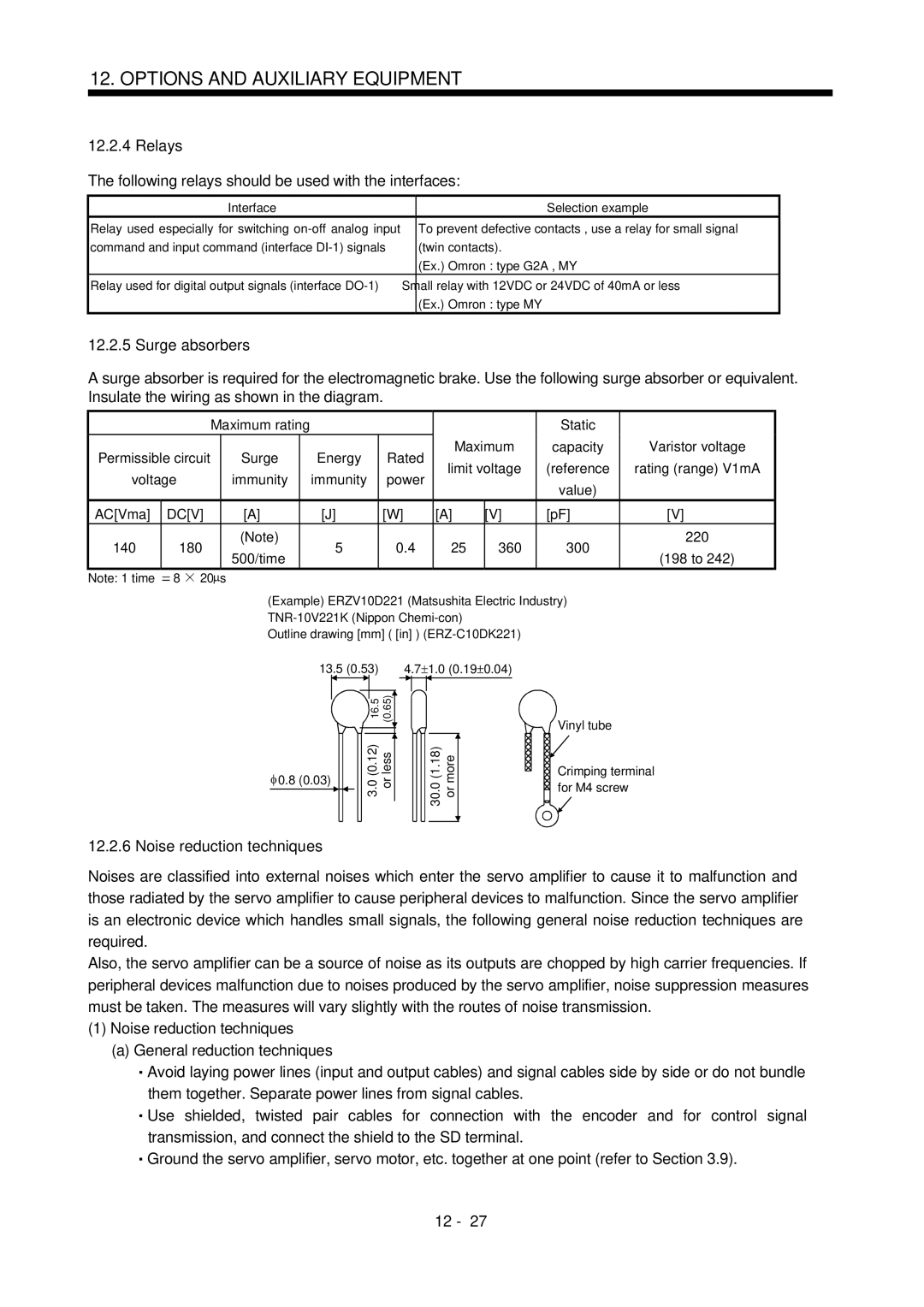
Surge absorbers
Relays
Following relays should be used with the interfaces
Noise reduction techniques
Options and Auxiliary Equipment
Noise reduction products
10 to 100MHZ 100 to 500MHZ 150
Ex A.2003
Outline drawing
On the output side, the number of turns must be four or less
Leakage current breaker Selection method
Selection example
SF1252
EMC filter
Combination with the servo amplifier
MR-J2S-200B MR-J2S-350B SF1253
HF3040-TM HF-3050A-TM
Absolute Position Detection System
Position setting again. Not doing so can cause runaway
Features
Absolute Position Detection System
Specifications Specification list
CN1 CN2
CON1
Confirmation of absolute position detection data
Sep SHNA030007-A
Revisions
Manual number is given on the bottom left of the back cover
SHNA030007-B