2 Installing a BigIron
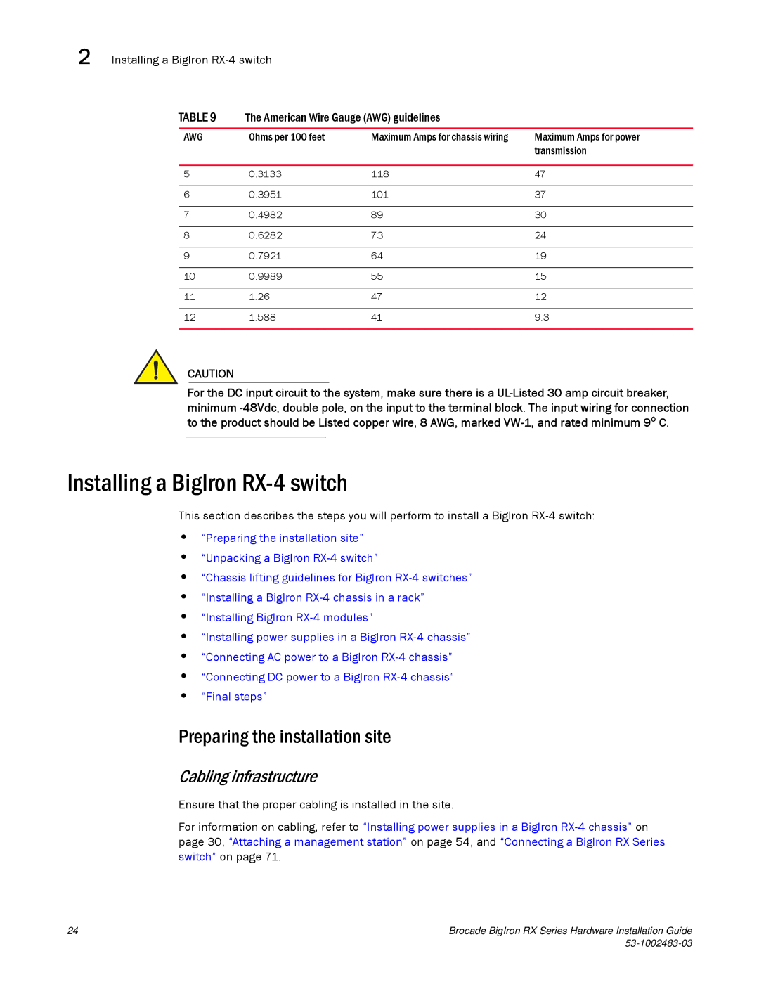
TABLE 9 | The American Wire Gauge (AWG) guidelines |
| |
|
|
|
|
AWG | Ohms per 100 feet | Maximum Amps for chassis wiring | Maximum Amps for power |
|
|
| transmission |
|
|
|
|
5 | 0.3133 | 118 | 47 |
|
|
|
|
6 | 0.3951 | 101 | 37 |
|
|
|
|
7 | 0.4982 | 89 | 30 |
|
|
|
|
8 | 0.6282 | 73 | 24 |
|
|
|
|
9 | 0.7921 | 64 | 19 |
|
|
|
|
10 | 0.9989 | 55 | 15 |
|
|
|
|
11 | 1.26 | 47 | 12 |
|
|
|
|
12 | 1.588 | 41 | 9.3 |
|
|
|
|
CAUTION
For the DC input circuit to the system, make sure there is a
Installing a BigIron RX-4 switch
This section describes the steps you will perform to install a BigIron
•“Preparing the installation site”
•“Unpacking a BigIron
•“Chassis lifting guidelines for BigIron
•“Installing a BigIron
•“Installing BigIron
•“Installing power supplies in a BigIron
•“Connecting AC power to a BigIron
•“Connecting DC power to a BigIron
•“Final steps”
Preparing the installation site
Cabling infrastructure
Ensure that the proper cabling is installed in the site.
For information on cabling, refer to “Installing power supplies in a BigIron
24 | Brocade BigIron RX Series Hardware Installation Guide |
|