|
|
| Hardware features | 1 |
TABLE 1 | Management module LEDs (Continued) |
|
| |
|
|
|
|
|
LED | Position | State | Meaning |
|
|
|
|
|
|
10/100/100 | Above and right | On (Green) | A link is established with the remote port. |
|
0 Ethernet | of |
|
|
|
Off | A link is not established with the remote port. |
| ||
Port | connector |
| ||
|
|
| ||
|
|
|
|
|
10/100/100 | Above and left of | On or blinking | The port is transmitting and receiving packets. |
|
0 Ethernet | (Yellow) |
|
| |
Port |
|
|
|
|
| Off for an | The port is not transmitting or receiving packets. |
| |
|
|
| ||
extended period
Interface modules
You can install up to 16 BigIron RX Series interface modules in the BigIron RX Series chassis as described:
•BigIron
•BigIron
•BigIron
NOTE
A BigIron RX Series interface module is dedicated, which means that you must install it in the BigIron RX Series chassis only. If you attempt to install a BigIron RX Series interface module in another Brocade chassis or an interface module intended for another Brocade chassis in the BigIron RX Series chassis, the module will not boot up to become active. Interface modules can be shared between BigIron
The interface modules are hot swappable, which means you can remove and replace them without powering down the system.
4-port 10 Gigabit Ethernet module
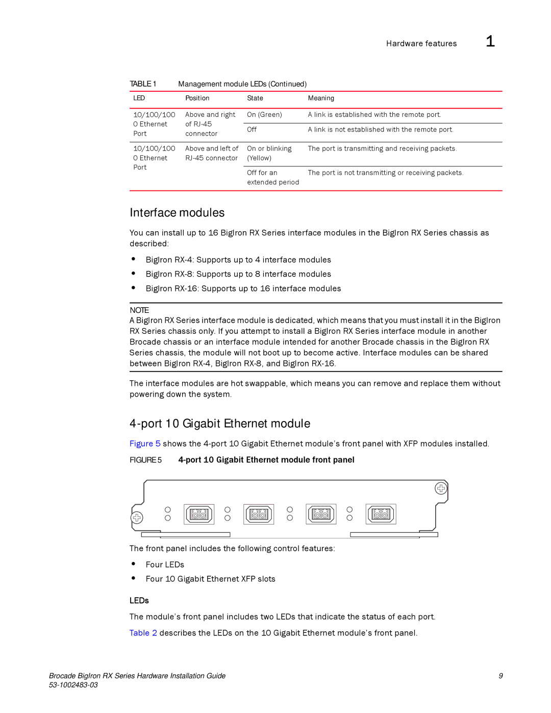
Figure 5 shows the 4-port 10 Gigabit Ethernet module’s front panel with XFP modules installed.
FIGURE 5 4-port 10 Gigabit Ethernet module front panel
The front panel includes the following control features:
•Four LEDs
•Four 10 Gigabit Ethernet XFP slots
LEDs
The module’s front panel includes two LEDs that indicate the status of each port. Table 2 describes the LEDs on the 10 Gigabit Ethernet module’s front panel.
Brocade BigIron RX Series Hardware Installation Guide | 9 |
|
