Brocade Communications Systems S3-1002483-03 manual Cooling system

Models: S3-1002483-03

1 206
Download 206 pages 54 b
Page 29
Image 29

Hardware features

1

Each power supply has three LEDs on its faceplate that provide status for the input power, output power and notification of alarms sent. If the input power and output power LEDs are on (a steady green), the power supply is providing power to the chassis components. The power supplies are hot swappable, which means you can remove and replace them without powering down the system.

DANGER

The power supplies are hot swappable, which means they can be removed and replaced while the BigIron RX Series chassis is powered on and running. However, Brocade recommends that you disconnect a power supply from its power source before removing and replacing it. The BigIron RX-8, or -16 chassis can be running while a power supply is being removed and replaced, but the power supply itself should not be connected to a power source. Otherwise, you could be injured or the power supply or other parts of the device could be damaged. (

Cooling system

The cooling system of BigIron RX Series switches is configured as described:

BigIron RX-4: Is equipped with a fan module containing two 4-speed fans.

BigIron RX-8: Is equipped with a fan module containing four 4-speed fans.

BigIron RX-16: Is equipped with three fan assemblies. The fan tray located in the lower front of the chassis contains six 4-speed fans. There are two fan assemblies located in the rear of the chassis. Each of these contain a 4-speed fan that pulls air through the chassis. The BigIron RX-16 is equipped with eight controllers to support redundancy.

NOTE

As shown in Figure 11 and Figure 12, the fans are located in the front of the BigIron RX-4 and BigIron RX-8 chassis. Figure 13 and Figure 14 show the front and rear locations of the fans on the BigIron RX-16. A new revision of the controller for the fan tray assemblies has been added for software release 02.2.01 and later. There is no visible change to the fan assemblies or the procedures for replacing the assemblies. Earlier software versions will not recognize the new controller.

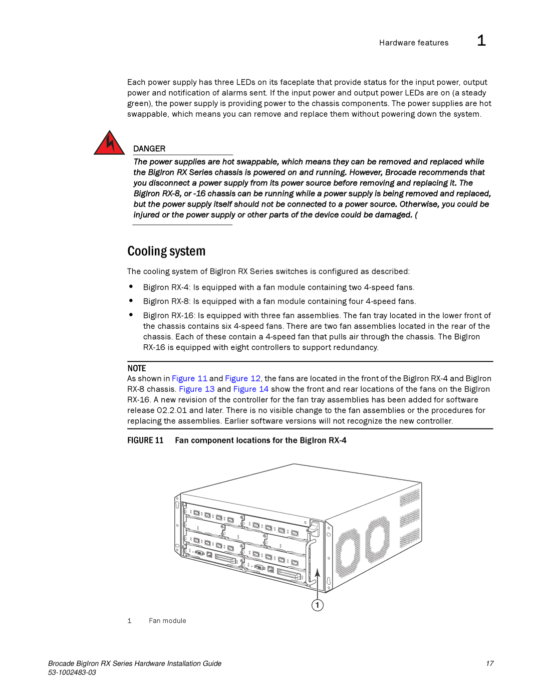
FIGURE 11 Fan component locations for the BigIron RX-4

1

1 Fan module

Brocade BigIron RX Series Hardware Installation Guide

17

53-1002483-03


Page 29
Image 29
Brocade Communications Systems S3-1002483-03 manual Cooling system, Fan component locations for the BigIron RX-4