Corporate Headquarters
Page
Copyright 1998-2004, Cisco Systems, Inc
Page
About This Guide Xiii
Chapter Product Overview
Chapter Preparing for Installation
Chapter Installing a Cisco 12008
Page
Chapter Troubleshooting the Installation
Chapter Running Diagnostics on the Cisco
Chapter Maintaining the Cisco
Appendix a Unpacking and Repacking the Cisco
Index
Page
Document Objectives
Audience
Document Organization
Document Organization
Document Conventions
Conventions Used in Command Descriptions
Document Conventions
Conventions Used in Examples
Conventions Used for Special Notices
About This Guide
World Wide Web
Obtaining Documentation
Obtaining Documentation
Obtaining Technical Assistance
Documentation CD-ROM
Ordering Documentation
Cisco Connection Online
Technical Assistance Center
Language Mail Address
Documentation Feedback
Obtaining Technical Assistance
Product Overview
Cisco’s Next Generation of Routers
Cisco’s Next Generation of Routers
Features of the Cisco 12008 Router
Features of the Cisco 12008 Router
Cisco 12008 supports the following features
Features of the Cisco 12008 Router
Overview of the Cisco
Overview of the Cisco
Major Components of the Cisco
Router Enclosure
Cable-Management System
Cable-Management System
Card Cage Fan Tray
Power Supply Fan Tray
AC-Input and DC-Input Power Supplies
AC-Input Power Supply
Operating Modes of the Power Supplies
DC-Input Power Supply
Features of the Power Supplies
Characteristics of the Power Supplies
AC-Input Power Supply Faceplate
AC-Input Power Supply Faceplate
Source AC Input Connector
Rotary Power Switch
AC-Input Power Supply LEDs
DC-Input Power Supply Faceplate
DC-Input Power Supply Faceplate
Circuit Breaker Alarm Terminal Block
Source DC Input Connectors
Circuit Breaker Position NC Contact No Contact
DC-Input Power Supply LEDs
Upper Card Cage and Associated Components
Upper Card Cage of the Cisco 12008 Router
Gigabit Route Processor
GRP Faceplate Horizontal Orientation Shown
Overview of the Cisco
GRP Memory Components
Dram
10 Locations of GRP Memory
Dram
Flash Memory
System Status LEDs
Soft Reset Switch
Asynchronous Serial Ports
Pcmcia Slots
Ethernet Port
Performance Route Processor
11 shows the front panel view of the PRP
Overview of the Cisco
12 PRP Horizontal Orientation
PRP Memory Components
PRP Memory Components
Type Size Quantity Description
Sdram
MEM-12KRP-FD64=
Soft Reset Switch
Flash Disk Slots
Ethernet Ports
Switch Fabric of the Cisco
Clock and Scheduler Card
Switch Fabric in the Cisco
Switch Fabric Controller Functions of the CSC
13 Block Diagram of the CSC
Overview of the Cisco
Housekeeping and Alarm Monitoring Functions of the CSC
14 CSC Alarm Monitoring Facilities
Overview of the Cisco
Overview of the Cisco
Board Power and Fan Tray Power Functions of the CSC
15 Status LEDs on an SFC
Cisco 12000 Series Line Cards
Quad OC-3c/STM-1c POS Line Card
16 Block Diagram of the Quad OC-3c/STM-1c POS Line Card
17 Quad OC-3c/STM-1c POS Line Card
Overview of the Cisco
Overview of the Cisco
OC-12c/STM-4c POS Line Card
18 Block Diagram of the OC-12c/STM-4c POS Line Card
19 OC-12c/STM-4c POS Line Card
Overview of the Cisco
Overview of the Cisco
20 Block Diagram of the OC-12c/STM-4c ATM Line Card
OC-12c/STM-4cATM Line Card
21 Front View of OC-12c/STM-4c ATM Line Card
Overview of the Cisco
Overview of the Cisco
Air Filter Assembly
Lower Card Cage and Associated Components
Switch Fabric Cards
22 Components in the Lower Card Cage
Power Distribution System in the Cisco
Power Distribution System in the Cisco
Ð48 VDC
Cisco 12008 Environmental Monitoring Facility
Cisco 12008 Environmental Monitoring Facility
System Specifications
System Specifications
Page
Power Supply Electrical Type Characteristic Value
Electrical Specifications of the AC-Input Power Supply
Electrical Specifications of the DC-Input Power Supply
Agency Approvals
Austel TS001
Agency Approvals Category
Agency Approvals
Preparing for Installation
Safety Recommendations
Safety Recommendations
Lifting Guidelines
Safety Recommendations
Preventing Electrostatic Discharge Damage
Laser Safety
Rack-Mounting Guidelines
Site Requirements Guidelines
Site Requirements Guidelines
Shows the outer dimensions of the Cisco 12008 enclosure
Side Front inches19.10
Air Flow Guidelines
Card Cage Fan Tray
Power Supply Fan Tray
Temperature and Humidity Guidelines
Internal Air Flow of the Cisco-Side View
Power Guidelines
AC-Powered Systems
Lists the source AC power cords available for the Cisco
DC-Powered Systems
Dimensions of the Lugs Used with the Source DC Power Cables
System Ground Connection Guidelines
System Ground Connection Guidelines
Site Wiring Guidelines
Site Wiring Guidelines
EMI Considerations
Synchronous Optical Network Connection Guidelines
Typical Fiber-Optic Link Attenuation and Dispersion Limits
Power Budget
Factor Single-Mode Multimode
Estimating Link Loss
Approximating the Line Card Power Margin
Link Loss Factor Estimate of Link Loss Value
Line Card Sonet Signal Requirements
Characteristic Single-Mode Multimode
Sonet Single-Mode Power Budget Example
Multimode Power Budget Example of Dispersion Limit
Single-Mode Transmission
Using Statistics to Estimate the Power Budget
Installation Tools Required
Installation Tools Required
Checking the Contents of the Shipping Container
Unpacking the Cisco
Using a Site Log
Using a Site Log
Sample Site Log
Using a Site Log
Installing a Cisco
Page
Installing the Mounting Brackets
Installing the Mounting Brackets
Installing the Mounting Brackets
Installing the Mounting Brackets Telco-Style Rack Shown
Removing Cards from the Upper Card Cage
Removing Components from the Router
Removing Components from the Router
Removing Components from the Router
Removing Cards from the Upper Card Cage CSC Shown
Removing a Power Supply from the Router
Removing a Power Supply from the Router
Rack-Mounting the Cisco
Rack-Mounting the Cisco
Lifting Handles for the Cisco
Installing the Router in the Rack
Reinstalling the Cards in the Upper Card Cage
Reinstalling Components in the Router
Reinstalling Components in the Router
Reinstalling the Power Supplies in the Router
Reinstalling Components in the Router
Connecting the Line Card Cables
Connecting the Line Card Cables
Connecting the Line Card Cables
Chassis Cable-management Tray a
Connecting Route Processor Cables
Connecting Route Processor Cables
GRP Console and Auxiliary Port Connection Equipment
Console and Auxiliary Port Connections
GRP Console Port Signals
GRP Console Port Signals
Pin Signal Direction Description
Auxiliary Port Signals
GRP Auxiliary Port Signals
GRP Ethernet Connection Equipment
RJ-45 and MII Ethernet Connections
Ethernet MII Receptacle
Ethernet MII Pinout Out Input/Output Description
Pin Signal
Ethernet RJ-45 Pinout
PRP Console and Auxiliary Port Connection Guidelines
10 Ethernet RJ-45 Receptacle
11 PRP Console and Auxiliary Port Connections
PRP Console Port Signals
PRP Auxiliary Port Signals
PRP Ethernet Connection Equipment
12 Using the Ethernet Port on the PRP
PRP Ethernet Connections
Ethernet Port Pin Signal Description
PRP RJ-45 Ethernet Receptacle Pinout
Crossover Cable Pinout for Connecting Two PRPs
Connecting an External Alarm Monitoring Facility
Ieee 802.3u Physical Characteristics
Connecting an External Alarm Monitoring Facility
16 DB-25 Connector and System Alarm LEDs on the CSC
17 Expanded View of the DB-25 Connector
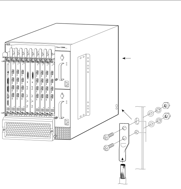
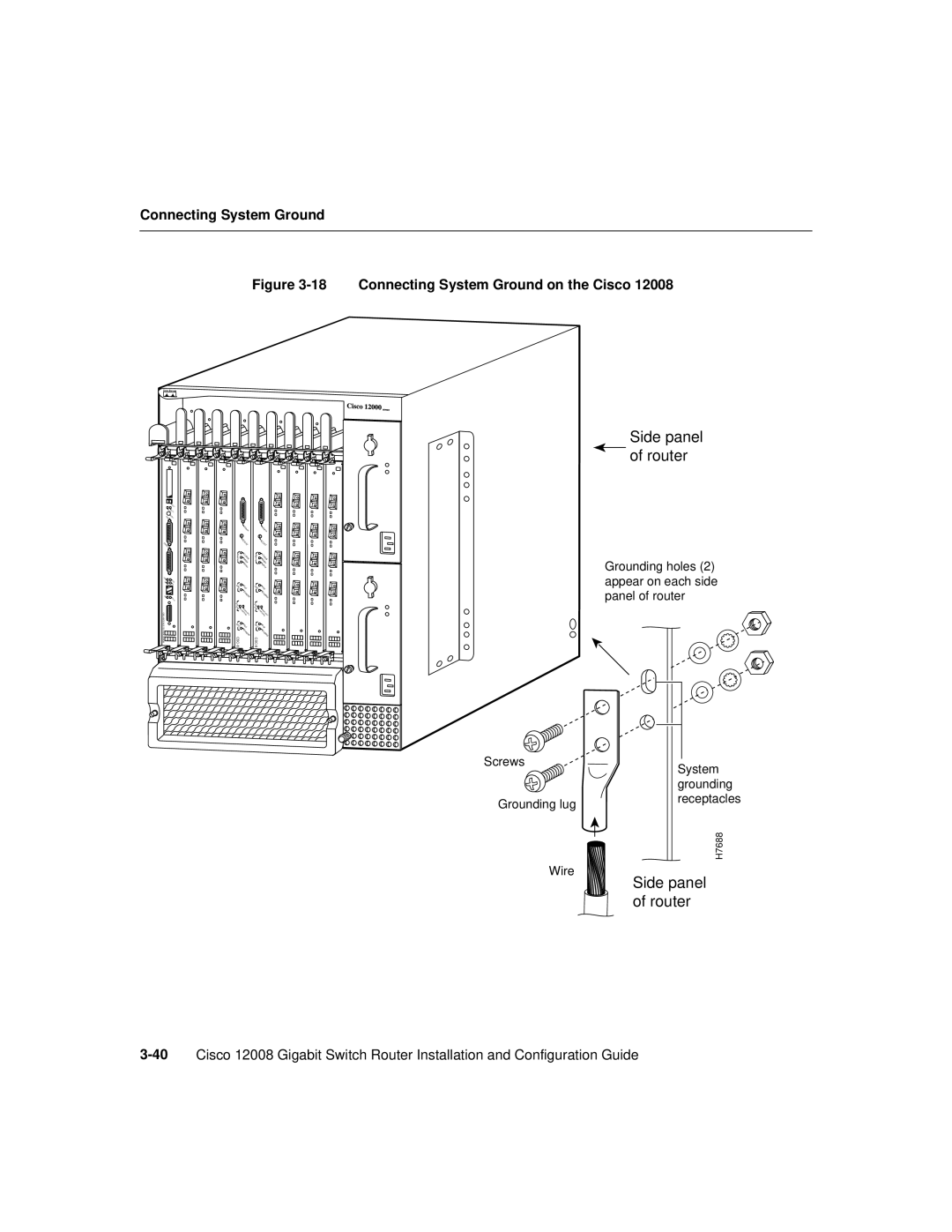
Connecting System Ground
Installing a Cisco 12008
Connecting System Ground
18 Connecting System Ground on the Cisco
Connecting Source Power to the Power Supplies
Connecting Source Power to the Power Supplies
Connecting Source Power to an AC-Input Power Supply
Connecting Source Power to the Power Supplies
Connecting Source Power to the Power Supplies
Connect power cord
Connecting Source Power to a DC-Input Power Supply
Connecting Source Power to the Power Supplies
Connecting Source Power to the Power Supplies
GND
Starting the Cisco
Starting the Cisco
Starting the Cisco
Starting the Cisco
Observing System Startup Performing a Basic Configuration
Sources of Cisco IOS Software
Sources of Cisco IOS Software
Checking Conditions Prior to System Startup
Checking Conditions Prior to System Startup
Starting the System and Observing Initial Conditions
Starting the System and Observing Initial Conditions
RP Alphanumeric LEDs Partial Faceplate View
Line Card Alphanumeric Displays Partial View Shown
Mrom
Starting the System and Observing Initial Conditions
Dir bootflash
Rommon 3 boot tftpgsr-p-mz.112-9.GS4 ip-address
Configuring the Cisco
Configuring the Cisco
Configuring the Cisco
Using the Setup Facility or the Setup Command
Configuring Global Parameters
Yes
YES Nvram
Enter the enable secret password when prompted to do so
Enter virtual terminal password bambam
Sample Display of Global Parameters
Configuring Network Interfaces
Configuring the Cisco
Configuring the Cisco
Configuring the Cisco
Use this configuration? yes/no
Routershow version
Using the Global Configuration Mode
Verifying the Running Configuration Settings
Ohm#sh run
Turing#sh run Building configuration Current configuration
Saving the Running Configuration Settings to Nvram
Reviewing the Running Configuration Settings
Router# show startup-config
No cdp enable Interface ATM4/0
Configuring the Software Configuration Register
Performing Other Configuration Tasks
Performing Other Configuration Tasks
Definition of Bits in the Software Configuration Register
Bit Number Hexadecimal Value Meaning/Function
Awaiting a user command to boot the system manually
Boot Field Settings and the Use of the Boot Command
Ciscobootfieldvalue-processorname
Changing the Software Configuration Register Settings
Exit the global configuration mode by entering Ctrl-Z
Meaning of Bits in the Software Configuration Register
Router# conf term
Default Boot Filenames Computed from Boot Field Bits
Action/File Name Bit
Console Baud Rate Settings
Destination
Bit Address net host
Baud Rate Bit
Recovering a Lost Password
Router#show version
Press Return
Using Flash Memory Cards in the RP
Router# show start-up config
Installing and Removing a Flash Memory Card in a RP
Installing and Removing a Flash Memory Card
Formatting a Flash Memory Card
Router# format slot0
Specifying a Cisco IOS Image for Booting the System
Console Commands Associated with Flash Memory Use
Dir
Enabling Booting from Flash Memory
Copying Files to a Flash Memory Medium
Copying a Cisco IOS Software Image onto a Flash Memory Card
Router# copy tftpmyfile1 slot0myfile1
Router# copy tftpnew.image slot0new.image
Copying Cisco IOS Software Images between Flash Memory Cards
Performing Other Configuration Tasks
Router# copy slot1image.new slot0image.new
Router# show boot
Copy startup-config slot0 slot1 filename
Router# copy running-config slot0myfile2
Recovering from Locked Blocks in Flash Memory Cards
Copy slot0 slot1 filename startup-config
Page
If You Need More Configuration Information
If You Need More Configuration Information
Troubleshooting the Installation
Troubleshooting Overview
Troubleshooting Overview
Normal System Status at Startup
Card LED Function Display Contents/LED Status/Meaning
Status of Alphanumeric Displays and LEDs at System Startup
Problem Solving Using a Subsystem Approach
Troubleshooting Overview
Identifying Startup Problems
Normal System Startup Sequence
Power Supply Status LEDs
Troubleshooting Overview
ENVM-2-FAN Fan has failed, shutdown in 2 minutes
Troubleshooting the Power Subsystem
Troubleshooting the Power Subsystem
Troubleshooting the Power Subsystem
Troubleshooting the Processor Subsystem
Troubleshooting the Processor Subsystem
Troubleshooting the RP
RP Alphanumeric Display Messages
Top Display Bottom Display Message
Troubleshooting the Line Cards
Line Card Alphanumeric Display Messages
CSC Alarm Functions
Troubleshooting the Cooling Subsystem
Troubleshooting the Cooling Subsystem
Troubleshooting the Cooling Subsystem
Troubleshooting the Cooling Subsystem
Additional Troubleshooting Reference Information
Additional Troubleshooting Reference Information
Running Diagnostics on the Cisco
Diagnostic Test Overview
Using the diag Command
Using the diag Command
Diagnostic Testing Sequence
Where
Loading and Running Diagnostics
Loading and Running Diagnostics
Diagnostic Examples
Without verbose Option
With verbose Option
Router# diag 2 verbose
Fdiagstatdone
Failed Diagnostic
Router# diag 7 verbose
Loading and Running Diagnostics
Maintaining the Cisco
Cleaning the Air Filter
Cleaning the Air Filter
Cleaning the Air Filter
Removing and Replacing the Air Filter Assembly
Installing and Removing a Blank Filler Panel
Installing and Removing a Blank Filler Panel
Installing a Blank Filler Panel in the Upper Card Cage
Adding an AC-Input Power Supply
Adding, Removing, or Replacing an AC-Input Power Supply
Adding, Removing, or Replacing an AC-Input Power Supply
Adding, Removing, or Replacing an AC-Input Power Supply
Faceplate of the AC-Input Power Supply
Adding, Removing, or Replacing an AC-Input Power Supply
Removing an AC-Input Power Supply
Connecting Power to an AC-Input Power Supply
Adding, Removing, or Replacing an AC-Input Power Supply
Replacing an Existing AC-Input Power Supply
Adding, Removing, or Replacing an AC-Input Power Supply
Verifying the Installation of an AC-Input Power Supply
Step
Adding, Removing, or Replacing a DC-Input Power Supply
Adding a DC-Input Power Supply
Adding, Removing, or Replacing a DC-Input Power Supply
Adding, Removing, or Replacing a DC-Input Power Supply
Dimensions of the Lugs Used with the Source DC Power Cables
Faceplate of the DC-Input Power Supply
Adding, Removing, or Replacing a DC-Input Power Supply
Adding, Removing, or Replacing a DC-Input Power Supply
Plastic Safety Shield on the DC-Input Power Supply
Adding, Removing, or Replacing a DC-Input Power Supply
Adding, Removing, or Replacing a DC-Input Power Supply
GND
Connecting Leads to the Circuit Breaker Alarm Terminal Block
Removing a DC-Input Power Supply
Adding, Removing, or Replacing a DC-Input Power Supply
Adding, Removing, or Replacing a DC-Input Power Supply
Replacing a DC-Input Power Supply
Adding, Removing, or Replacing a DC-Input Power Supply
Adding, Removing, or Replacing a DC-Input Power Supply
Adding, Removing, or Replacing a DC-Input Power Supply
Adding, Removing, or Replacing a DC-Input Power Supply
Verifying the Installation of a DC-Input Power Supply
Removing and Replacing the Fan Trays
Removing and Replacing the Fan Trays
Removing the Fan Tray from the Lower Card Cage
Removing and Replacing the Fan Trays
10 Removing the Card Cage Fan Tray from the Router
Installing a Fan Tray in the Lower Card Cage
11 Inserting the Card Cage Fan Tray into the Router
Removing the Power Supply Fan Tray
12 Removing the Power Supply Fan Tray from the Router
Installing the Power Supply Fan Tray
13 Inserting the Power Supply Fan Tray into the Router
Checking the Installation of a Fan Tray
Status LEDs for the Fan Trays
Status LEDs for the Fan Trays
Status LEDs State Description
14 Fan Tray Status LEDs on the CSC
Removing and Replacing the RP
Removing and Replacing the RP
Removing the RP
Removing and Replacing the RP
Installing the RP
15 Removing the RP Cisco 12012 Shown
Removing and Replacing the RP
Removing and Replacing Switch Cards
Checking the Installation of the RP
Removing and Replacing Line Cards
Removing and Replacing Line Cards
Removing and Replacing Switch Cards
Removing an SFC
16 Removing an SFC
Installing an SFC
17 Installing an SFC
Removing a CSC
18 Removing a CSC
Installing a CSC
Checking the Installation of Switch Cards
19 Installing a CSC
20 Status LEDs on a CSC
Status LEDs for the CSC State Description
Status LEDs for the SFCs
21 Status LEDs on an SFC
Removing a Cable-Management Tray
Removing and Replacing the Cable Management System
Removing and Replacing the Cable Management System
22 Cable-Management Tray on a Cisco
23 Removing an Interface Cable from Cable-Management Tray
24 Removing the Cable-Management Tray from the Cisco
Installing a Cable-Management Tray
25 Installing a Cable Management Tray
Removing a Cable-Management Bracket
26 Removing Interface Cables from a Line Card
27 Removing the Cable-Management Bracket
Installing a Cable-Management Bracket
28 Attaching a Cable-Management Bracket to a Line Card
29 Installing Interface Cables onto a Line Card
Upgrading Memory on a Line Card
Upgrading Memory on a Line Card
Backplane connector P4 Dram bank Tx Dimm Rx Dimm
Dram Dimm
Memory Sockets Dimm Module Provided Product Number
Removing a Line Card from the Router
Captive screw Line card Cable-management Bracket
Line card Grasp card carrier to
Removing a Dimm from a Line Card
Installing a New Dimm on a Line Card
Reinstalling a Line Card in the Router
Checking the Installation of Line Card Memory
Upgrading Memory on the RP
Upgrading Memory on the RP
Unpacking and Repacking the Cisco
Cisco 12008 Packaging Materials
Cisco 12008 Packaging Materials
Figure A-1 Components of the Cisco 12008 Packaging System
Unpacking/Packing Tools
Unpacking/Packing Tools
D E
AC-input power
EDO DRAM, GRP
Installing a card 47 to
MDI
Pcmcia
Sdram
Weight Squeeze command