18-1
DLP-F300 Install Fiber-Optic Cables for Sncp Configurations
18-2
DLP-F302 Change Tunnel Type
18-3
DLP-F303 Delete Overhead Circuits
Click the Provisioning Overhead Circuits tabs
18-4
DLP-F304 Repair an IP Tunnel
18-5
J1 Function Cards
Selecting the Edit Path Trace Option
18-6
18-7
18-8
DLP-F306 Provision Path Trace on STM-N Ports
Click Circuits
18-9
DLP-F307 Create Login Node Groups
Click the Login Node Group tab
Click Create Group
18-10
Tools
18-11
DLP-F310 Change the JRE Version
18-12
DLP-F311 Remove Pass-through Connections
18-13
DLP-F312 Delete a Node from a Specified Login Node Group
DLP-F313 Change a Circuit Service State
18-14
DLP-F314 Provision MS-DCC Terminations
18-15
Node view, click the Provisioning Comm Channels MS-DCC tabs
18-16
DLP-F315 Provision a Proxy Tunnel
Click the Provisioning Network Proxy subtabs
18-17
DLP-F316 Provision a Firewall Tunnel
Click the Provisioning Network Firewall subtabs
18-18
DLP-F317 Delete a Proxy Tunnel
DLP-F318 Delete a Firewall Tunnel
Click the Provisioning Comm Channels MS-DCC tabs
DLP-F319 Change an RS-DCC Termination
DLP-F320 Change an MS-DCC Termination
Click the Provisioning Comm Channels RS-DCC tabs
18-20
DLP-F321 Delete an RS-DCC Termination
DLP-F322 Delete an MS-DCC Termination
Node view, click the Provisioning Comm Channel RS-DCC tabs
18-21
Click the Provisioning Comm Channel MS-DCC tabs
18-22
DLP-F324 Provision Asap Ethernet Ports
Click the Provisioning Ethernet Ports tabs
18-23
DLP-F325 Provision Asap POS Ports
Click the Performance Ethernet Ether Ports Statistics tabs
Click the Provisioning Ethernet POS Ports tabs
18-24
DLP-F326 View Asap STM-N PM Parameters
Click the Performance Ethernet POS Ports Statistics tabs
Click the Performance Optical tabs Figure
18-25
DLP-F327 View Asap Ether Ports Statistics PM Parameters
Ether Ports Statistics in the Card View Performance Window
18-26
18-27
DLP-F328 View Asap Ether Ports Utilization PM Parameters
18-28
DLP-F329 View Asap POS Ports Statistics PM Parameters
18-29
DLP-F330 View Asap POS Ports Utilization PM Parameters
18-30
DLP-F331 View Asap POS Ports History PM Parameters
18-31
DLP-F332 Change Node Access and PM Clearing Privilege
18-32
18-33
DLP-F333 Install the Asap Carrier Modules
18-34
DLP-F334 Verify Pass-Through Circuits
18-35
DLP-F335 Preprovision an SFP
18-36
DLP-F336 Print CTC Data
18-37
DLP-F337 View Asap Ether Ports History PM Parameters
18-38
18-39
Click the Provisioning MS-SPRing tabs
Click Create MS-SPRing
18-40
DLP-F339 Create a Two-Fiber MS-SPRing Manually
18-41
DLP-F340 Change an MS-SPRing Node ID
18-42
DLP-F341 MS-SPRing Exercise Ring Test
18-43
DLP-F342 MS-SPRing Switch Test
18-44
Click the Maintenance MS-SPRing tabs
Click Retrieve
18-45
18-46
18-47
DLP-F344 Initiate an MS-SPRing Manual Ring Switch
DLP-F343 Provision an STM-N Circuit Route
18-48
DLP-F345 Clear an MS-SPRing Manual Ring Switch
Onsite/Remote Onsite Security Level Provisioning or higher
18-49
DLP-F346 Create an MS-SPRing on a Single Node
18-50
DLP-F347 Initiate an MS-SPRing Force Ring Switch
18-51
DLP-F348 View Circuit Information
Sncp
2F-PCA
DRI
PCA
18-53
18-54
Pendingmerge
Droppending
18-55
11 Connecting Fiber to a Four-Node, Two-Fiber MS-SPRing
18-56
DLP-F350 Delete an MS-SPRing from a Single Node
12 Selecting Single Roll Attributes
18-57
14 Selecting a New Endpoint
18-58
15 Viewing the Rolls Tab
18-59
18-60
18-61
18-62
Click the Circuits tab
17 Selecting Dual Roll Attributes
18-63
18-64
18 Setting Roll Routing Preferences
18-65
18-66
18-67
18-68
18-69
DLP-F356 Delete a Roll
Click the Circuits Rolls tabs
18-70
DLP-F357 Cancel a Roll
DLP-F358 Provision a Multirate PPM
18-71
DLP-F359 Change the Optical Line Rate
Click the Provisioning Pluggable Port Modules tabs
18-72
DLP-F360 Delete a PPM
18-73
DLP-F361 Provision OSI Routing Mode
18-74
Node view, click the Provisioning OSI Tarp Config tabs
DLP-F362 Provision or Modify Tarp Operating Parameters
18-75
18-76
Node view, click the Provisioning OSI Tarp Static TDC tabs
Click Add Static Entry
18-77
DLP-F365 Add a Tarp Manual Adjacency Table Entry
Click Delete Static Entry
18-78
Click the Provisioning OSI Routers Setup tabs
DLP-F366 Provision OSI Routers
18-79
DLP-F368 Enable the OSI Subnet on the LAN Interface
DLP-F367 Provision Additional Manual Area Addresses
18-80
DLP-F369 Create an IP-Over-CLNS Tunnel
Click the Provisioning OSI Tunnels tabs
18-81
DLP-F370 Remove a Tarp Manual Adjacency Table Entry
18-82
DLP-F371 Change the OSI Routing Mode
18-83
DLP-F372 Edit the OSI Router Configuration
18-84
DLP-F373 Edit the OSI Subnetwork Point of Attachment
DLP-F374 Edit an IP-Over-CLNS Tunnel
Node view, click the Provisioning OSI Routers Subnet tabs
18-85
DLP-F375 Delete an IP-Over-CLNS Tunnel
18-86
DLP-F376 View IS-IS Routing Information Base
18-87
DLP-F377 View ES-IS Routing Information Base
DLP-F378 Manage the Tarp Data Cache
18-88
DLP-F379 Export CTC Data
19 Selecting CTC Data for Export
18-89
18-90
DLP-F380 Configure the Node for Radius Authentication
20 Radius Server Tab
18-91
18-92
DLP-F381 Delete a Server Trail
Click the Provisioning Server Trails tabs
18-93
DLP-F383 Download an Alarm Severity Profile
DLP-F382 Grant Superuser Privileges to a Provisioning User
18-94
18-95
DLP-F384 Install the Asap 1PIO and 4PIO PIM Modules
22 1PIO Module Faceplate
18-96
18-97
DLP-F385 Consolidate Links in Network View
18-98
24shows a network view with unconsolidated DCC and PPC links
18-99
ALL
Dwdm GCC, OTS, PPC TDM
18-100
DLP-F386 Adjust the Java Virtual Memory Heap Size
DLP-F387 Install an SFP/XFP
18-101
DLP-F388 Remove an SFP/XFP
18-102
DLP-F389 Remove a 1PIO or 4PIO PIM Module
Click the Provisioning Optical Line tabs
DLP-F390 Provision an Optical Line Rate and Wavelength
Asap 4PIO
1PIO
18-104
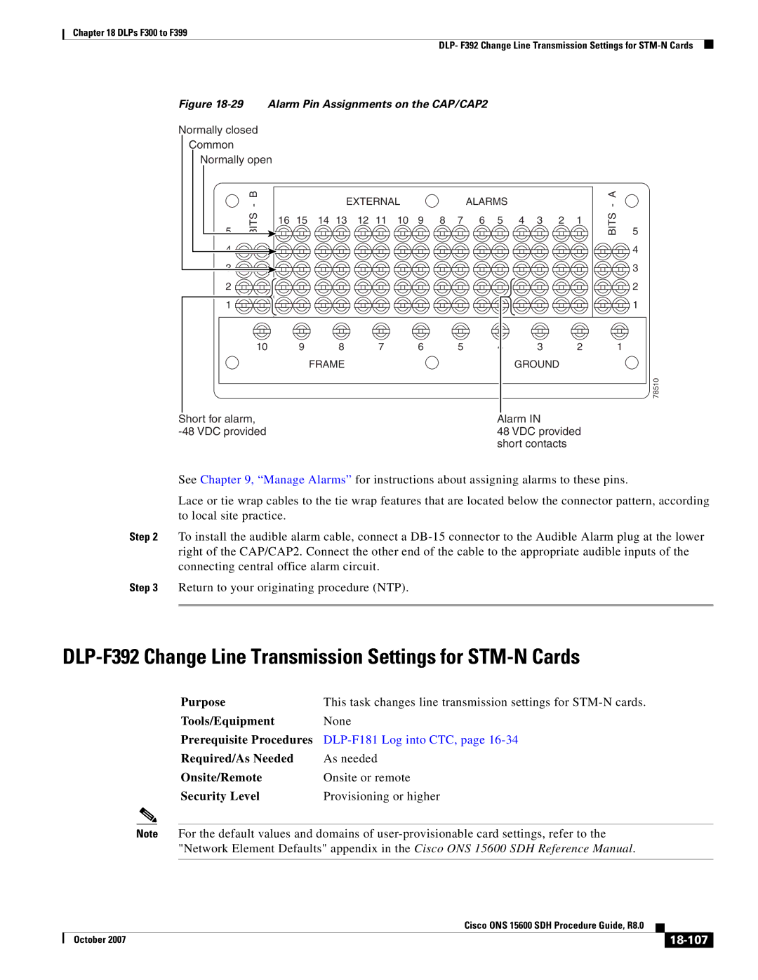
DLP-F391 Install Alarm Wires on the CAP/CAP2
CAP/CAP2
27 Rear of the ONS 15600 SDH, Including the CAP/CAP2
18-105
28 CAP/CAP2 Faceplate and Connections
18-106
18-107
DLP-F392 Change Line Transmission Settings for STM-N Cards
18-108
SF BER
SD BER
18-109
Sonet
18-110
Sets
STU
18-111
DLP-F393 Change Threshold Settings for STM-N Ports
18-112
18-113
DLP-F394 Change Optics Threshold Settings for STM-N Ports
18-114
Refresh
18-115
DLP-F395 Change the STM-N Port ALS Maintenance Settings
Click the Maintenance ALS tabs
18-116
DLP-F396 Clear All PM Thresholds
18-117
DLP-F397 Provision the Designated Socks Servers
18-118
18-119
18-120