Chapter 18 DLPs F300 to F399
DLP- F349 Install
Caution Do not provision the
Note To avoid error, connect
Note See Table
Step 1 Plan your fiber connections. Use the same plan for all
Step 2 Plug the fiber into the Tx connector of an
Step 3 Repeat Step 2 until you have configured the ring.
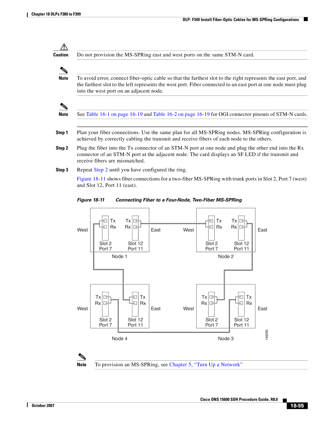
Figure 18-11 shows fiber connections for a two-fiber MS-SPRing with trunk ports in Slot 2, Port 7 (west) and Slot 12, Port 11 (east).
Figure 18-11 Connecting Fiber to a Four-Node, Two-Fiber MS-SPRing
West
|
|
|
|
|
| Tx | Tx |
|
|
|
|
|
|
|
|
|
| Rx | Rx |
|
|
|
|
|
|
|
|
|
|
|
|
|
| ||
|
|
|
|
|
|
|
|
|
|
|
|
|
| Slot 2 | Slot 12 | ||||||||
| Port 7 | Port 11 | |||||||||
Node 1
EastWest
|
|
|
|
| Tx | Tx |
|
|
|
|
|
|
|
|
|
|
|
| Rx | Rx |
|
|
|
|
|
|
|
|
|
|
|
|
|
|
|
|
|
|
| ||
|
|
|
|
|
|
|
|
|
|
|
|
|
|
Slot 2 | Slot 12 | ||||||||||||
Port 7 | Port 11 | ||||||||||||
Node 2
East
West
Tx | Tx | Tx | Tx |
Rx | Rx | Rx | Rx |
| East | West |
|
Slot 2 | Slot 12 | Slot 2 | Slot 12 |
Port 7 | Port 11 | Port 7 | Port 11 |
| Node 4 |
| Node 3 |
East
134293
Note To provision an
|
| Cisco ONS 15600 SDH Procedure Guide, R8.0 |
|
| |
|
|
| |||
| October 2007 |
|
|
|
|
|
|
|
| ||