HP Color Laserjet Enterprise CP5520
Page
HP Color LaserJet Enterprise CP5520 Printer Series
Trademark Credits
Copyright and License
Conventions used in this guide
Conventions used in this guide
Table of contents
Enww
Removal and replacement
101
Enww
Solve problems 253
Enww
294
Xiii
414
Enww
459
Xvii
480
Xix
Parts and diagrams 551
Appendix B Product specifications 641
Appendix a Service and support 631
Appendix C Regulatory information 643
Index 655
Theory of operation
Basic operation
Product block diagram
Major product systems
Normal sequence of operation
Sequence of operation
1Sequence of operation
Name Timing Purpose
Print
Formatter-control system
Sleep mode
Memory
Input/output
PJL overview
Firmware
Control panel
PML
2Engine-control system
Engine-control system
DC controller
3DC controller diagram
Component type Abbreviation Name
2Electrical components
Enww
Motors
Motors
Description Components driven Failure Detection
Motors
Description Area cooled Type Speed
Fans
TH4 Fuser Heater
Fuser-control circuit
7Fuser-heater control circuit
Fuser temperature control
Fuser protective function
Fuser failure detection
SW1
Low-voltage power supply
Enww
Overcurrent/overvoltage protection
9High-voltage power supply
High-voltage power supply
Enww
10Laser/scanner system
Laser scanner system
Laser failure detection
Electrophotographic process
Image-formation system
12Electrophotographic process drive system
13Image formation process
Image formation process
Pre-exposure
Latent-image formation block
Primary charging
16Laser beam exposure
Laser beam exposure
17 Developing
Developing block
Primary transfer
Transfer block
Secondary transfer
Separation
Fusing block
Drum cleaning block
ITB cleaning block
Print cartridges
24Print cartridge block diagram
Cartridge presence detection
Memory tag
Toner level detection
Cartridge life detection
25Developing unit engagement and disengagement control
ITB
ITB unit
Primary transfer roller engagement and disengagement control
ITB unit presence detection
ITB cleaning mechanism
SW6 ITB
Calibration
29Color-misregistration control
Color-misregistration control
Image stabilization control
Environment change control
Image density control Dmax
Image halftone control Dhalf
30Pickup, feed, and delivery system
Pickup, feed, and delivery system
31Pickup, feed, and delivery system blocks
Photo sensors
Photo sensors and switches product
Description
Pickup and feed block
Motors and solenoids
6Motors and solenoids paper path
34Tray 2 cassette pickup operation
Tray 2 cassette pickup
35Tray 2 cassette multiple-feed prevention
Tray 2 cassette multiple-feed prevention
Enww
Tray 2 cassette lift-up operation
36Tary 2 cassette lift-up operation
Cassette media-presence detection
Tray 1 MP tray paper pickup
SL2
Tray 1 MP tray last-paper detection
39Tray 1 MP tray last-paper detection
Paper feed
40 Paper feed
41Skew-feed prevention
Skew-feed prevention
Media detection sensor types
Media detection
Auto Sense mode Print mode Media Speed Sensor Detection
Fusing and delivery block
Feed-speed control
Loop control
42 Loop control
Pressure roller pressurization and depressurization control
44Output bin full detection
Output bin full detection
Duplex reverse and duplex feed control
Duplex block duplex models only
SL3
Duplex operation
Print mode Duplex print
Paper size Duplexing media feed mode
Paper sizes, duplex operation
Print modes, duplex operation
Product detects the following jams
Jam detection
After the TOP sensor detects the trailing edge
48Paper-feeder paper path
Paper feeder
10Paper-feeder motors
Paper-feeder motors
Motor Driving part Failure detection
11Paper-feeder electrical components
Paper-feeder paper pickup and feed
Component type Abbreviation Description
Paper-feeder cassette lift operation
SR3
Paper-feeder jam detection
543X500-sheet paper deck
Optional 3X500-sheet paper deck
Component Description
3X500-sheet paper deck
133X500-sheet paper deck
14Paper deck motors
Motor control
Component Component driven Failure Detection
Pickup-and-feed operation
Component Signal
15Pickup-and-feed operation
Paper Deck Cassette 3 Pickup Motor Control
Cassette lift-up operation
58Cassette lift-up operation
59Jam detection
Enww
Removal and replacement
Introduction
Removal and replacement strategy
Electrostatic discharge
1Phillips and pozidrive screwdriver comparison
Required tools
Before performing service
Service approach
After performing service
Post-service test
Replace print cartridges
Removal and replacement procedures
Enww
Enww
Close the front door Removal and replacement
3Remove the toner-collection unit 2
Toner-collection unit
Enww
Administration Manage Supplies Reset Supplies New Fuser Kit
Reset the New Fuser Kit setting at the control panel
Fuser
Pickup roller Tray
7Remove the pickup roller Tray 1 2 Removal and replacement
Separation pad Tray
Insert the tool under the separation pad
13Remove the separation roller assembly Tray 2 2
Separation roller assembly Tray
Open Tray Open the right-door assembly
15Remove the 1 x 500 or 3 x 500 rollers 1
Enww
Secondary transfer roller
Intermediate transfer belt ITB
Enww
Reset the New Transfer Kit setting at the control panel
21Remove the formatter 1
Formatter PCA
Enww
Before proceeding, remove the following components
Hard Drive
Identify the hard drive type
Remove the encrypted HDD
26Remove the solid-state hard drive 1
Remove the solid-state hard drive
Remove the lock from the PCA
Identification and location
Covers
External panels, covers, and doors
1External panels, covers, and doors
31Remove the right-front cover and control-panel assembly 2
Right-front cover and control-panel assembly
Enww
Left cover
Remove the rear cover
Rear cover
36Remove the toner collection unit access door 2
Toner collection unit access door
Enww
38Remove the right-rear cover
Right-rear cover
39Right-rear cover ground spring Removal and replacement
Reinstall the right-rear cover
Remove the top cover
Top cover
Enww
42Remove the front-door assembly 1
Front-door assembly
44Remove the front-door assembly 3 Removal and replacement
45Remove the front-door assembly 4
46Remove the right-door assembly 1 Removal and replacement
Right-door assembly
48Remove the right-door assembly 3
Disconnect two connectors callout
51Remove the right-door assembly 6
Formatter case
Main assemblies
Remove the formatter case
53Remove the formatter case assembly 2
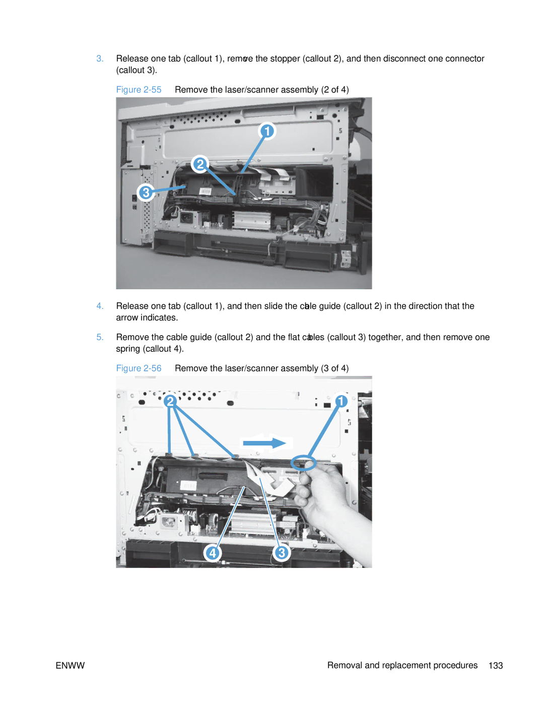
Remove the laser/scanner assembly
Laser/scanner assembly
56Remove the laser/scanner assembly 3
Enww
Remove the paper pickup assembly
Paper pickup assembly
Disconnect four connectors callout
61Remove the paper pickup assembly 4
Reinstall the paper pickup assembly
63Paper pickup assembly sensor flag correctly installed
Reset the New Registration Roller menu item
Installing a replacement paper pickup assembly
Device Maintenance Service Service Access Code
Reset the Media Sensor Value
Enww
Remove the registration sensor assembly
Registration sensor assembly
Enww
Enww
Remove the lifter-drive assembly
Lifter-drive assembly
Enww
Enww
ITB front guide assembly
75Remove the ITB front guide assembly 3
Enww
77Remove the ITB rear guide assembly
ITB rear guide assembly
Remove the residual toner full sensor
Residual toner full sensor
79Remove the residual toner full sensor 2
80Remove the residual toner full sensor 3
Reinstall the residual toner full sensor
Enww
Remove the main drive assembly
Main drive assembly
87Remove the main drive assembly 3 Removal and replacement
89Remove the main drive assembly 5
90Remove the main drive assembly 6 Removal and replacement
92Remove the main drive assembly 8
94Remove the main drive assembly 10 Removal and replacement
96Remove the main drive assembly 12
98Remove the main drive assembly 14 Removal and replacement
100Remove the main drive assembly 16
101Remove the main drive assembly 17 Removal and replacement
102Install the main drive assembly 1
Install the main drive assembly
104Install the main drive assembly 3 Removal and replacement
See -103 Install the main drive assembly 2 of 8 on
108Install the main drive assembly 7 Removal and replacement
109Install the main drive assembly 8
Remove the fuser drive assembly
Fuser drive assembly
Disconnect two connectors callout
Original fuser drive assembly Proceed to the next step
Install a replacement fuser drive assembly
Enww
Remove the fuser gear assembly
Fuser gear assembly
118Remove the fuser gear assembly 3
120Remove the fuser gear assembly 5 Removal and replacement
122Remove the fuser gear assembly 7
Enww
124Remove the fuser gear assembly 9
Original fuser gear assembly Proceed to the next step
Install a replacement fuser gear assembly
Enww
Remove the delivery assembly
Paper delivery assembly
Reinstall the paper delivery assembly
129Remove the paper delivery assembly 2
Enww
Remove the duplex-drive assembly
Duplex drive assembly duplex models
Remove three screws callout
Remove the delivery drive assembly
Delivery drive assembly simplex models
Remove the residual-toner-feed assembly
Residual-toner-feed assembly
138Remove the residual-toner-feed assembly 2
Remove the ITB motor
ITB motor M1
140Remove the ITB motor 2
Remove the drum motor
Drum motor M2
Remove the developing motor
Developing motor M3
Remove the fuser motor
Fuser motor M4
Remove the developing-disengagement motor
Developing-disengagement motor M6
Remove the power-supply fan
Power-supply fan FM1
Enww
Enww
Remove the fuser fan
Fuser fan FM2
150Remove the fuser fan 3 Removal and replacement
Enww
Remove the formatter fan and ICB PCA
Formatter fan FM3 and ICB PCA
154Remove the formatter fan 3
Enww
Remove the DC controller PCA
DC controller PCA
Enww
Remove the low-voltage power supply
Enww
162Remove the low-voltage power supply 3
Enww
Remove the imaging developing high-voltage power supply
Imaging developing high-voltage power supply
Remove the first transfer high-voltage power supply
First transfer high-voltage power supply
166Reinstall the first transfer high-voltage power supply
Remove the second transfer high-voltage power supply
Second transfer high-voltage power supply
168Remove the second transfer high-voltage power supply 2
Remove the driver PCA
Driver PCA
170Remove the driver PCA 2
Remove the power switch PCA
Power switch PCA
Remove the environmental sensor
Environmental sensor
500 rear cover
500-sheet paper feeder assembly
175Remove the 1 x 500 left cover 2
500 left cover
Enww
500 right-front cover
500 front-upper cover
500 right door
180Remove the 1 x 500 right door 3 Removal and replacement
181Remove the 1 x 500 right-lower cover
500 right-lower cover
500 pickup assembly
184Remove the 1 x 500 pickup assembly 3
Enww
187Remove the 1 x 500 lifter-drive assembly 2
500 lifter-drive assembly
500 pickup motor
188Remove the 1 x 500 pickup motor Removal and replacement
189Remove the 1 x 500 driver PCA
500 driver PCA
190Remove the 3 x 500 rear cover Removal and replacement
500-sheet paper feeder optional accessory
191Remove the 3 x 500 right and left cassette rails
500 right and left cassette rails
500 paper deck controller PCAs
194Remove the 3 x 500 paper deck lifter-drive assembly 2
500 paper deck lifter-drive assembly
500 paper deck pickup motor
196Remove the 3 x 500 front-lower cover
500 front-lower cover
500 left cover
199Remove the 3 x 500 right-corner cover
500 right-corner cover
500 front-upper cover
500 right-door assembly
Enww
204Remove the 3 x 500 right-lower cover
500 right-lower cover
500 left-lower cover
Remove the 3 x 500 rear-lower cover
500 rear-lower cover
Remove the 3 x 500 paper deck pickup assembly
500 paper deck pickup assembly
Enww
Solve problems
Solve problems checklist
Solve problems checklist
Administration Reports Configuration/Status Pages
Current settings pages
Print the current settings pages
Menu map
Sign In menu
Control panel menus
Retrieve Job From USB menu
Retrieve Job From Device Memory menu
3Retrieve Job From Device Memory menu
Supplies menu
4Supplies menu
Enww
Trays menu
Trays menu
General Settings menu
Administration menu
7General Settings menu
Reports menu
Enww
Enww
Enww
Enww
Print Settings menu
Retrieve From USB Settings menu
8Retrieve From USB Settings menu
Print Settings menu
Print Options menu
9Print Settings menu
10Print Options menu
Product supports
Enww
Display Settings menu
Display Settings menu
12Manage Supplies menu
Manage Supplies menu
13Manage Trays menu
Manage Trays menu
14Network Settings menu
Network Settings menu
15Embedded Jetdirect
Keep
Embedded Jetdirect
First level
16Troubleshooting menu
Troubleshooting menu
Backup/Restore menu
Device Maintenance menu
USB Firmware Upgrade menu
Calibration/Cleaning menu
17Backup/Restore menu
Calibration/Cleaning menu
Automatic Calibrations Disabled Enabled
Service menu
Determine the problem source
Troubleshooting process
Pre-troubleshooting checklist
General topic Questions
Troubleshooting flowchart
Troubleshooting flowchart
Power-on checks
Power subsystem
Power-on troubleshooting overview
Boot sequence
Power-on timing approximate
Component diagnostics
Tools for troubleshooting
LED diagnostics
Understand lights on the formatter
Heartbeat LED
Engine diagnostics
Defeat the right-door opening/closing sensor PS15
Defeating interlocks
Administration Troubleshooting Diagnostic Tests
Disable cartridge check
Engine test button
Paper-path test
Sensor or switch name Sensor or switch number
20Manual sensor diagnostic tests
Manual sensor test
Developer alienation sensor PS11 ITB alienation sensor
Front-door opening/closing switch PS14
Right-door opening/closing sensor PS15
5Test the right-door opening/closing switch 1 Solve problems
Enww
TOP top-of-page sensor PS5
Fuser loop sensors 1 and 2 PS7 and PS8
Fuser pressure-release sensor PS9
Fuser output sensor PS6
Developer alienation sensor PS11
ITB alienation switch SW5
21Tray/Bin manual sensor test
Tray/Bin manual sensor test
Enww
Tray 1 paper sensor PS2
Tray 2 paper present sensor PS1
Tray 2 paper surface sensor PS4
Tray 2 paper size switches SW7 and SW8
Tray 3 paper sensor SR3
Tray 3 paper surface sensor SR2
Tray 3 paper size sensors SW2 and SW3
Tray 3 feed sensor SR1
Tray 3 door opening/closing sensor SW1
Tray 4 paper surface sensor SR2
Tray 4 paper sensor SR3
Tray 4 paper size sensors SW2 and SW3
Tray 4 feed sensor SR1
Tray 5 paper surface sensor SR82
Tray 5 paper sensor SR83
Tray 5 paper size sensors SW82 and SW83
Tray 5 feed sensor SR81
Output-bin-full sensor PS10
Paper-path sensors test
Print/stop test
22Paper-path sensors diagnostic tests
Component tests
Component test special-mode test
23Component tests 1
Fuser Contact/Alienation Drive
Switchback Motor
TrayX Pickup Motor
DuplexerPickup Motor
Full/half speed intake fan
Additional component tests
24Component tests 2
Speed controlled intake fan
Full speed intake fan
Component test Component tested Comments Fuser Fan
Formatter Fan
Block diagrams
Diagrams
26Optional paper feeder Tray 3 cross section
Plug/jack locations
DC controller connections
Location of connectors
DC controller connections
25DC controller connections
28Product connections 1
Product connections
29Product connections 2
30Product connections 3
31Product connections 4
32Product connections 5
33Product connections 6
34Paper feeder connections
35External component locations
Locations of major components
36Major component locations 1
Main drive unit Lifter drive unit
37Major component locations 2
38Major component locations 3
39Motors, fans, and rollers component locations
40PCA component locations
Timing chart 1
General timing charts
42General timing chart 2
Fuser
General circuit diagram
44 General circuit diagram 2
Paper feeder general circuit diagram 1 X
46Paper deck general circuit diagram 3 X
Administration Troubleshooting Print Quality Pages
Print-quality-troubleshooting pages
Internal print-quality test pages
Yellow Green
50Black print-quality troubleshooting
Diagnostics
Enww
Process a cleaning
Clean the paper path
Device Maintenance Calibration/Cleaning
Set up an auto cleaning
Configuration
Configuration
51Configuration
HP embedded Jetdirect
Security Settings information
26Important information on the configuration pages
Finding important information on the configuration pages
Accessories and internal storage
Diagnostics menu
Color-band test
Repetitive image-defect ruler
Print quality troubleshooting tools
Calibrate the product
27Sign In menu
Sign In menu
Personal identification number PIN
Might not be available
Retrieve Job From USB menu
29Retrieve Job From Device Memory menu
Retrieve Job From Device Memory menu
Supplies menu
Settings Cartridge Prompt to
Supplies menu
30Supplies menu
Color/Black Auto
Transfer Kit Very Low Stop
Mix Mostly Color
Trays menu
Alternative Letterhead Disabled Mode Enabled
Use another tray Enabled Disabled
Size/Type Prompt Display Do not display
Blank Pages Auto
Reports menu
Administration menu
31Trays menu
32Reports menu
Other Pages Print
Map
33General Settings menu
General Settings menu
Midtones Cyan Density
Enww
Sets the sensing option for Tray 1 for paper types using
Adjust Paper
When Expanded
Sense Mode
Sensing
Humidity Mode Normal High
Optimize Normal Paper Standard
Paper Curl Mode Normal
Light Media Normal
Envelope Control Normal
Cleaning Control Normal
Environment Normal
Line Voltage Normal Low Voltage
When thin vertical
When a background
When the other
Correct the problem
Moisture Control Normal Alternate
Alternate Alternative 1 to
Normal is
Jam Recovery Auto
Maximum is
Week Default Folder
Held Timeout Hour
Quick Copy Job Off
Name for Stored
Restrict Color Enable
Settings Calibration
Print Settings menu
Retrieve From USB Settings menu
Retrieve From USB Settings menu
Font Pitch Range 0.44 Default =
35Print Settings menu
Append CR to LF Yes
Dimension Range 5.00 Default =
Default Custom Paper Inches Dimension
Print Options menu
36Print Options menu
Enable Edge to Edge Enabled
Dimension Range 127 Default =
Overrides Disabled
Millimeters
Display Settings menu
Manage Supplies menu
Supply Settings Black Cartridge Very Low Stop
38Manage Supplies menu
Status menu to
Notifies you when
Color/Black Mix Auto Mostly Color Pages Mostly Black
39Manage Trays menu
Manage Trays menu
First level Values
Alternative Letterhead Mode Disabled
Use another tray Enabled
First level Values Description Manually Feed Prompt Always
Size/Type Prompt Display
First level Values Description Blank Pages Auto
Network Settings menu
Network Settings menu
First level Values Description Timeout
Method
Default IP Auto IP
Release and Dhcp Renew
Release
Address Manual Enable
0.0 IPv6 Settings Enable
Settings Off
Xxx.xxx.xx Secondary
Router
Router Router Specified Policy
Router Unavailable If a
Https Optional Access
Idle Timeout The time
802.1x Reset
00080
Test
Diagnostics Embedded LAN HW Test Yes
Http Test Yes
Select All Yes
Data Path Yes
Tests
Execution
Print Results Yes
127.0.0.1 Dest IPv6
Ping Results Packets Sent
00000
Ping Yes Progress
Enww
42Troubleshooting menu
Troubleshooting menu
Paper Path Test Print Test
Sensors
Test Duplex Path Off
Number
Sensor Test
Repeat option
Repeat Off
Diagnostic Data
Retrieve Export to USB
Debug
Cleanup Debug Off
Information File
Include Crash Off
Backup/Restore menu
Device Maintenance menu
43Backup/Restore menu
Backups
Cleaning Interval setting
Calibration/Cleaning menu
44Calibration/Cleaning menu
USB Firmware Upgrade menu
Cycle Counts Mono Cycle Counts
Service menu
Refurbish Cycle
Glass Cleaning
Cold Reset Paper Letter
New Registration Yes
Roller
Memory error
10.0X.Y0 Supply memory error
Description
Label missing
10.22.51
10.22.50
10.22.52
10.23.50
10.23.52
10.23.51
Printing past very low
10.XX.34 Used supply in use
10.XX.40 Genuine HP supplies installed
10.XX.70 Printing past very low
10.XX.41 Unsupported supply in use
10.YY.25 Wrong cartridge in color slot
10.YY.15 Install supply
Fuser kit 10.31.15
10.YY.35 Incompatible supply
13.00.00
YY Internal clock error
13.A3.FF
13.D3.DZ
13.WX.FF
13.WX.EE
13.WX.YZ Fuser area jam
13.WX.YZ Fuser wrap jam
13.WX.YZ Jam in lower right door
13.WX.YZ Jam below control panel
13.WX.YZ Jam in right door
13.WX.YZ Jam in middle right door
13.WX.YZ Jam in Tray
Too complex
Insufficient memory To continue, press OK
32.1C.XX
Enww
Recommended action
Enww
Enww
32.21.00
Unsupported USB accessory detected To continue, press OK
USB I/O buffer overflow To continue, press OK
Embedded I/O buffer overflow To continue, press OK
Embedded I/O bad transmission To continue, press OK
Error
YZ Unexpected size in tray
LBP OHT
YZ Unexpected type in tray
LBP OHT
YZ Error To continue, press OK
Enww
47.00.XX
42.XX.YY
47.01.XX
47.02.XX
47.03.XX
47.WX.YZ Printer calibration error To continue, press OK
47.04.XX
47.05.00
47.FC.23
Recommended action = 1 or W =
50.WX.YZ Fuser error To continue, turn off then on
Enww
= B
= a
52.XX.00 Error To continue, turn off then on
YY Error
Recommended action 54.00.03
54.XX.YY Error
54.00.06 or 54.00.14 or
54.01.05
54.0X.07
54.11.05 or
54.0X.0B or 54.0X.0C
54.0X.0D or 54.0X.0E
YY DC controller error To continue, turn off then on
YY Error To continue, turn off then on
55.0X.YY DC controller error To continue, turn off then on
57.00.0Y Error To continue, turn off then on
Recommended action 57.00.01
57.00.03
57.00.02
Recommended action 59.00.30 or
59.00.90 or 59.00.A0
59.00.F0
59.0X.50 Error To continue, turn off then on
Recommended action 59.05.50
59.06.50 or 59.07.50 or
59.0X.70 Error To continue, turn off then on
59.0X.60 Error To continue, turn off then on
59.0X.80 Error To continue, turn off then on
Recommended action 50.05.80
60.00.0Y Tray Y lifting error
50.06.80 or 50.07.80 or
Recommended action 60.00.02
60.00.05 or
61.00.01
80.0X.YY Embedded JetDirect error
Error To continue, turn off then on
No system To continue, turn off then on
Enww
Corrupt data in solutions volume
Corrupt data in firmware volume
Corrupt data in configuration volume
Corrupt data in job data volume
Upgrade not performed timeout during receive
Upgrade not performed file is corrupt
Upgrade not performed error writing to disk
Upgrade not performed error reading upgrade
Upgrade not performed the file is invalid
Upgrade canceled by user
99.00.2X
Unknown disk
Unsupported disk
No disk data installed
Disk data error
Disk is not bootable please download firmware
Incorrect disk
Binname Full Remove all paper from bin
99.XX.YY
Supply almost full
Supply low or Supplies low
Supplyvery low or Supplies very low
Tray X lifting
File System file operation failed To clear, press OK
File System device failure To clear, press OK
File System file system is full To clear, press OK
File System is not initialized
Canceling
Calibration reset pending
Canceling... jobname
Bad optional tray connection
Cleaning
Cleaning do not grab paper
Checking engine
Checking paper path
Clearing paper path
Clearing event log
Close front door
Close lower right door
Close right door
Close middle right door
Close upper right door For help press ?
Cooling device
Data received To print last page, press OK
Creating cleaning
EIO X disk initializing
EIO X disk not functional
EIO X disk spinning up
HP Secure Hard Drive disabled
Event log is empty
Expected drive missing
Incompatible supplies
Incompatible supply
Initializing
Install supply Close rear door
Install supply
Install Fuser Unit
Install Transfer Unit
Install supplies
Internal disk not functional
Load Tray X Type, Size
Internal disk spinning up
Load Tray X Type, Size To use another tray, press OK
Loading program XX Do not power off
Manually feed Type, Size
Manually feed Type, Size To use another tray, press OK
No job to cancel
Moving solenoid
Moving solenoid and motor
Performing Color Band Test
Paused
Performing Paper Path Test
Please wait
Printing Diagnostics
Printing Configuration
Printing Color Usage Log
Printing Demo
Printing Font List
Printing File Directory
Printing Fuser Test
Printing Help
Printing Registration
Printing PQ Troubleshooting
Printing RGB Samples
Printing stopped
Processing... filename
Processing duplex job Do not grab paper until job completes
Processing... copy X of Y
Ready IP Address
Ready
Remove all print cartridges
Remove at least one print cartridge
Replace supply
Replace supplies
Restore Factory Settings
Rotating color motor
Restricted from printing in color
Rotating motor
Size mismatch in Tray
Supplies in wrong positions
Sleep mode on
Tray X empty Type, Size
Tray X open
Tray X overfilled
Troubleshooting
Type mismatch Tray
Unsupported drive installed To continue, press OK
Unsupported USB accessory detected Remove USB accessory
Unsupported tray configuration
USB accessory not functional
Wrong cartridge in color slot
53Sample event log
Event-log messages
Print the event log from the Service menu
Print the event log from the Administration menu
View an event log from the Administration menu
Print an event log
Clear an event log
Viewing the event log from the Service menu
Clear jams
Product is jammed Cause Solution
Common causes of jams
54Jam locations
Jam locations
46Paper path jam sensors
500-sheet feeder use a SR1 tray feed sensor
Jam event code Jammed paper location
47Event codes for jams
Fuser modes for jam event codes Z
Enww
Clear jams in the upper-right door
Enww
Clear jams in the lower-right door
Clear jams in Tray
Enww
Clear jams from Tray 2, Tray 3, or an optional tray
Clear jams in the output bin area
Jams in the output bin
Jam causes and solutions
Jams in the fuser and transfer area
52Causes and solutions for duplexing reverse jams
51Causes and solutions for fuser delivery stationary jams
53Causes and solutions for duplex repick jams
Jams in the duplex area duplex models only
55Causes and solutions for pickup delay jam 1 tray pickup
54Causes and solutions for residual media jams
Jams in Tray 1, Tray 2 and internal paper path
Door assembly. See Right-door assembly on
56Causes and solutions for pickup delay jams Tray
Causes and solutions for residual media jams
57Causes and solutions for pickup stationary jams
Jams in Tray 3, 4, 5,
58Causes and solutions for residual media jams
Replace any defective parts
Set the jam recovery feature
Change jam recovery
Administration General Settings Jam Recovery
Product feeds multiple sheets Cause Solution
Solve paper-handling problems
Product feeds incorrect page size Cause Solution
Product feeds multiple sheets
Paper does not feed automatically Cause Solution
Product pulls from incorrect tray Cause Solution
Product pulls from incorrect tray
Paper does not feed automatically
Transparencies or glossy paper will not feed Cause Solution
Paper does not feed from Tray 2, 3, 4, 5, or Cause Solution
Transparencies or glossy paper will not feed
Envelopes jam or will not feed in the product
Output is curled or wrinkled Cause Solution
Output is curled or wrinkled
Product will not duplex or duplexes incorrectly
Set to Up to resolve print-quality issues caused by poor
61MP modes under the Adjust Paper Types sub menu
Use manual print modes
Or rough surface media
62MP modes under the Optimize submenu
Humidity Mode
Media Temp
Print quality examples
Solve image-quality problems
Problem Sample Cause Solution
Item in the Calibration/Cleaning
Execute the Clean Laser Glass
Maintenance menu
Defective
Power-supply
Enww
Cleaning kit CC468-67919 is
Clean the paper path
Clean the product
Set up an auto cleaning
Problem Cause Solution
Solve performance problems
Supplies very low message is
Solve direct-connect problems
Solve connectivity problems
Solve network problems
Problem Solution
Service menu
Service mode functions
Automatic Calibrations
Test Support Continuous Print from
Restore factory-set defaults
Product resets
Restore factory-set defaults values
Partial Clean
Clean Disk and Partial Clean functions
Active and repository firmware locations
Print
Characteristics of a Partial Clean
Clean Disk
Reasons for performing Partial Clean
Execute a Partial Clean
Execute a Clean Disk
Reasons for performing Clean Disk
Access the Preboot menu
Preboot menu options
Cold reset using the Preboot menu
63Preboot menu options 1
Partial Clean
Clean Disk
Password Clear
Password
64Preboot menu options 2
Disk Device
65Preboot menu options 3
External
66Preboot menu options 4
67Preboot menu options 5
68Preboot menu options 5
Determine the installed revision of firmware
Product updates
Perform a firmware upgrade
Embedded Web Server
USB storage device Preboot menu
USB storage device control-panel menu
Enww
Parts and diagrams
Order parts, accessories, and supplies
Order parts by authorized service providers
1Order parts, accessories, and supplies
Supplies part numbers
Customer self repair parts
3Supplies part numbers
Description Part number
Enww
Part number CSR level Solid state drive kit CE707-67901
Service replacement parts
Fuser drive unit CE707-67904
4Accessories part numbers
Accessories part numbers
How to use the parts lists and diagrams
Assembly locations
1External covers, panels, and doors
External covers, panels, and doors
Description Part number Qty
External covers, panels, and doors
Simplex Model
Right door assembly
Right door assembly
3Internal components 1
Internal components 1
7Internal components 1
4Internal components 2
Internal components 2
8Internal components 2
Duplex Model
Internal components 3
9Internal components 3
6Internal components 4
Internal components 4
10Internal components 4
7Internal components 5
Internal components 5
11Internal components 5
8Internal components 6
Internal components 6
12Internal components 6
9Internal components 7
Internal components 7
13Internal components 7
10Internal components 8
Internal components 8
14Internal components 8
11Internal components 9
Internal components 9
15Internal components 9
1x250 cassette
121x250 cassette Parts and diagrams
Description Part number Qty Cassette CE710-67906
1x250 cassette
13Paper pick-up assembly
Paper pick-up assembly
Paper pick-up assembly
14Paper delivery assembly Parts and diagrams
Paper delivery assembly
Paper delivery assembly
15 PCAs
Printed circuit assemblies
PCAs
1x500PF external components
1x500 paper feeder
1x500PF external components
171x500PF internal components
1x500PF internal components
1x500PF internal components
18 1x500PF PCA
1x500PF PCA
22 1x500PF PCA
3x500PF external components
3x500 paper feeder
3x500PF external components
20 3x500PF internal components
3x500PF internal components
3x500PF internal components
3x500PF cassette
213x500PF cassette Parts and diagrams
Description Part number Qty Cassette 3x500PF RM1-6942-000CN
3x500PF cassette
22 3x500PF PCAs
3x500PF PCAs
263x500PF PCAs
27Alphabetical parts list
Alphabetical parts list
Internal components 3
Internal components 2
PCAs on
3x500PF PCAs on
Gear, 25T, duplex model RU6-0772-000CN
Guide, slide RC2-7203-000CN
Imaging high-voltage PCA RM1-6800-000CN
Lifter plate assembly, Tray RM1-6043-030CN
Paper delivery assembly
Rail, cassette, right 3x500PF RL1-1390-000CN
Sensor, right door WG8-5696-000CN
Spring, tension, front RU6-2727-000CN
28Numerical parts list
Numerical parts list
Part number Description
RC2-6547-000CN Guide, fuser, rear
RC2-6650-000CN Cover, main cross-member cable
RC2-6715-000CN Hinge, front cover, right
RC2-6842-000CN Guide, cable, right
RC2-7201-000CN Slider, push
RC2-9331-000CN Cover, left 1x500PF
RK2-2276-000CN Fan, power supply
RM1-6012-000CN Waste toner cover assembly
RM1-6742-000CN Driver PCA duplex model
RM1-6944-000CN Paper pick-up assembly 1x500PF
RM1-7914-060CN Gear assembly, fuser
RU6-2744-000CN Spring, tension, rear
Enww
Service and support
Hewlett-Packard limited warranty statement
Enww
Enww
Data stored on the print cartridge
End User License Agreement
Transfer
Customer self-repair warranty service
Customer support
Enww
Product specifications
Table B-1Product dimensions
Physical specifications
Product Height Depth Width Weight
Environmental condition Recommended Allowed
Regulatory information
FCC regulations
Environmental product stewardship program
United States and Puerto Rico
Return and recycling instructions
Non-U.S. returns
Material restrictions
Paper
HP Color LaserJet Enterprise CP5520 Printer Series
Enww
Declaration of Conformity
October
Boise, Idaho USA
For regulatory topics only
Types of memory
Certificate of Volatility
Volatile memory
Non-volatile memory
Laser safety
Safety statements
Vcci statement Japan Power cord instructions
Power cord statement Japan
Varoitus
Luokan 1 laserlaite
Varo
GS statement Germany
Accessories
Symbols/Numerics
LED
Msds
Recycling
Quality
Sensor SW1
483 Supplies menu, control panel 258 Support Online 639
Page
CE707-90935* *CE707-90935