Administrator’s Handbook
Pinhole Configuration Procedure. Use the following steps:
1.From the Configure toolbar button
Since Port Forwarding is required for this example, the Motorola Netopia® embedded Web server is con- figured first.
☛NOTE:
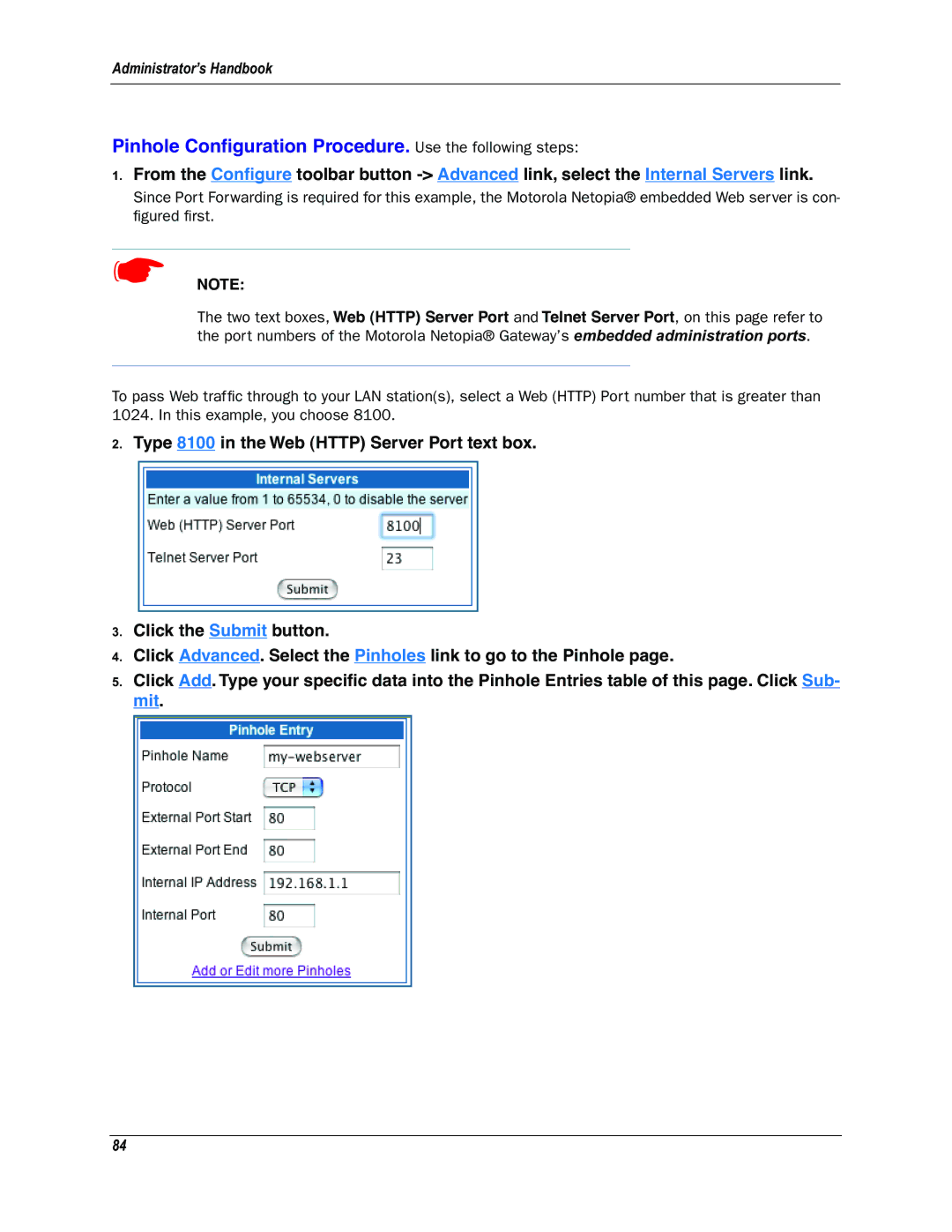
The two text boxes, Web (HTTP) Server Port and Telnet Server Port, on this page refer to the port numbers of the Motorola Netopia® Gateway’s embedded administration ports.
To pass Web traffic through to your LAN station(s), select a Web (HTTP) Port number that is greater than 1024. In this example, you choose 8100.
2.Type 8100 in the Web (HTTP) Server Port text box.
3.Click the Submit button.
4.Click Advanced. Select the Pinholes link to go to the Pinhole page.
5.Click Add. Type your specific data into the Pinhole Entries table of this page. Click Sub- mit.
84
