MC55
MC55 AT Command Set
Contents
ATSM20
AT+CSCS
Atscfg
AT+CMER
Atslck
Atspic
AT+CLCK
AT+CPWD
AT+CSNS
AT+CR
AT+CRC
Atscni
AT+CGAUTO
AT+CGACT
AT+CGANS
AT+CGDATA
AT+FRH
AT+FOPT
AT+FREV
AT+FRM
Atsstr
Atssta
Atsstgi
AT+CPBR
ATS3
Atsctm
Atssync
ATS4
List of Tables
List of Figures
Introduction
Scope of the document
Related documents
Document conventions
Quick reference table
PIN
Superscript notation for parameters and values
AT+CXXX=?
AT command syntax
Using parameters
AT+CXXX?
Combining AT commands on the same command line
Supported character sets
IRA
Ascii
BSP
Null
GSM alphabet tables and UCS2 character values
Mobile
GSM
2 UCS2 and GSM data coding and conversion for SMS text mode
Cscs
UCS2
Cscs GSM UCS2
Mobile
Flow Control
Software flow control XON/OFF flow control
Hardware flow control RTS/CTS flow control
Unsolicited Result Code Presentation
Communication between Customer Application and MC55
Common PCN Handset Specification Cphs
CSP
Errors and Messages
Configuration Commands
AT&Fvalue
Valuenum
AT&Vvalue
AT&V Display current configuration
1 AT&V responses
Active Profile
Active Profile
+FCLASS
+CGSMS
ERROR/+CME Error err
AT&Wvalue
ATQ Set result code presentation mode
ATQn
ATVvalue
ATV Set result code format mode
Verbose and numeric result codes
If value=0 If value=1
Connect 9600/RLP
Connect 2400/RLP
Connect 4800/RLP
Connect 14400/RLP
ATX Set Connect result code format and call monitoring
ATXvalue
ATZ Set all current parameters to user defined profile
ATZvalue
AT+CFUN=?
OK Error +CME Error
AT+CFUN Set phone functionality
+CFUN fun
Funnum
Rstnum
AT+CFUN? +CFUN AT+CFUN=1
AT+CFUN=0
+CMTI SM,5
AT+CFUN=1,1
Wake up the ME from Sleep mode
Fun=0
URC
Atsmso
Atsmso Switch off mobile station
ATSMSO=?
Smso MS OFF OK
AT+GCAP
10 AT+GCAP Request complete TA capabilities list
AT+GCAP=?
+GCAP name
AT+CMEE=?
11 AT+CMEE Report mobile equipment error
OK Error
AT+CMEE?
Summary of CME Errors related to GSM
AT+CMEE=2
Summary of GPRS-related CME Errors
Summary of CMS Errors related to GSM
No +CNMA ACK Expected
Mobile
12 AT+CSCS Select TE character set
AT+CSCS=?
AT+CSCS?
Also see chapter Supported character sets
ATSCFG=?
Atscfg Extended Configuration Setting
+CME Error operation temporary not allowed
ATSCFG?
Scfg PowerSaver/Mode9/Timeout, cfun9-timeout
URC indication via Ring line ATSCFG=URC/Ringline, uri
Cfun9-timeoutstr+CSCS
HandOverStatusstr+CSCS
SCFGAudio/AMR,0065006E00610062006C00650064
SCFGAudio/AMR,enabled
AT+CSCS=UCS2
AT+CSCS=GSM ATSCFG?
AT+CSCS=GSM
ATSM20?
ATSM20 Set M20 compatibility mode
ATSM20=?
SM20CallMode, CmgwMode
CallModenum
CmgwModenum
AT+CMER=?
Status Control Commands
AT+CMER Mobile Equipment Event Reporting
AT+CMER?
+CIEV indDescr, indValue
Mobile
AT+CIND Indicator control
AT+CIND=?
AT+CIND?
Command Description
ATSLCC, AT+CLCC or Atscni
Also refer Call Status Information
Statenum
AT+CPIN=9999
+CIEV call,1 +CIEV sounder,0 +CIEV call,0
ATD0123456
+CIEV sounder,1
No Carrier
ATSIND=?
Atsind Extended Indicator Control
ATSIND=indDescr, Mode
ATSIND?
User
Issued
AT+CEER
AT+CEER Extended error report
AT+CEER=?
+CEER locationID, reason, ssRelease
AT+CHLD=2 OK AT+CHLD=3
Cause Location ID for the extended error report
AT+clck=oi,1,0000,3 +CME Error incorrect password
+CEER 35,0,43
GSM release cause for L3 Radio Resource RR
Siemens release cause for L3 Radio Resource RR
GSM release cause for Mobility Management MM
Siemens release cause for L3 Mobility Management MM
GSM release cause for L3 Call Control CC
Mobile
Siemens release cause for L3 Call Control CC
Siemens release cause for L3 Advice of Charge AOC
GSM Release cause for Supplementary Service Call
Mobile
Siemens release cause for Session Management SM
GSM cause for L3 Protocol module or other local cause
Siemens release cause for Gprs API
Siemens release cause for Embedded Netcore
ATS18=n
ATS18 Extended call release report
ATS18?
+CAUSE locationID, reason
Busy
Connect 9600/RLP
AT+CPAS
AT+CPAS Mobile equipment activity status
AT+CPAS=?
+CPAS pas
AT+WS46?
AT+WS46 Select wireless network
AT+WS46=?
AT+WS46=n
AT\Q Flowcontrol
Serial Interface Control Commands
Error
AT\Qn
AT&C Set circuit Data Carrier Detect DCD function mode
AT&Cvalue
AT&D Set circuit Data Terminal Ready DTR function mode
AT&Dvalue
AT&S Set circuit Data Set Ready DSR function mode
AT&Svalue
ATE Enable command echo
ATEvalue
AT+ILRR Set TE-TA local rate reporting
AT+ILRR=?
AT+ILRR?
Ratenum
AT+IPR?
AT+IPR Set fixed local rate
AT+IPR=?
+IPR rate
Chronized after restarting the GSM engine see chapter
Autobauding
AT+CMUX=?
AT+CMUX Enter multiplex mode
+CMUX mode
AT+CMUX?
Restrictions on Multiplex mode
Subsetnum
+++
ATS8
ATS6
ATS7
ATS10
Second serial interface ASC1
AT+CFUN
AT+CPIN=?
Security Commands
AT+CPIN Enter PIN
AT+CPIN?
Pinstr
New pintext
Codetext
PH-C PIN
What to do if PIN or password authentication fails?
PH-SP PUK
PH-C PUK
Mobile
AT+CPIN2?
AT+CPIN2 Enter PIN2
AT+CPIN2=?
+CPIN2 code
AT+CPIN2? +CPIN2 SIM PUK2
New pinstr
AT+CPWD=P2,0000,8888
AT+CPIN2=12345678,8888
AT+CPBW=2,+493012345678,145,Charly
+CME Error
AT+CPBS=FD
AT+CPIN2=8888 AT+CPBW=2,+493012345678,145,Charly
ATSPIC?
Atspic Display PIN counter
ATSPIC=?
Atspic
Counternum
Facilitystr
+CPIN SIM PIN
+CPIN SIM PUK
At+cpin=9999 OK at+cpin?
At+cpin=4714 +CME Error incorrect password Atspic Spic
AT+CLCK=facility, mode, password, class
AT+CLCK Facility lock
AT+CLCK=?
Phone security locks set by client or factory
Factory defined SIM locks
Classnum
Passwordstr
Statusnum
SMS
AT+CLCK=SC,2
AT+CPIN? +CPIN SIM PIN
AT+CPIN=3333
AT+CPIN=1111
AT+CPIN? +CPIN PH-SIM PIN
AT+CLCK=PS,0,3333
ATSLCK=facility, mode, password, class
Atslck Facility lock
ATSLCK=?
AT+CPWD=facility, old password, new password
AT+CPWD Change Password
+CPWDlist of supported facility, password length
+CME Error 16 +CME Error incorrect password
Password length 4 to 8 digits
Password length 4 digits
Password lengthnum
Old passwordstr
New passwordstr
AT+CPWD=PS,12345678,1111
AT+CPWD=AO,0000,3333
AT+CPWD=PS,1111,2222
AT+CPWD=PS,12345678
ATSPWD=facility, old password, new password
Atspwd Change Password
SPWDlist of supported facility, password length
ATSPWD=?
ATI
Identification Commands
ATI Display product identification information
ATIvalue
AT+CGMI Request manufacturer identification
AT+CGMI=?
AT+CGMI
AT+GMI Request manufacturer identification
AT+GMI=?
AT+GMI
AT+CGMM Request model identification
AT+CGMM=?
AT+CGMM
AT+GMM Request TA model identification
AT+GMM=?
AT+GMM
AT+CGMR
AT+CGMR Request revision identification of software status
AT+CGMR=?
Xx.yystr
AT+GMR=?
AT+GMR
Xx.yytext
AT+CGSN=?
AT+CGSN
AT+GSN=?
AT+GSN
AT+CIMI
10 AT+CIMI Request international mobile subscriber identity
AT+CIMI=?
Imsi
Call related Commands
Call Status Information
Call Status Information
ATA
Connect text TA switches to data mode
ATA Answer a call
Textstr
ATDnmgsm
No Dialtone
Connect text
Mgsmstr
ATD03022222222
ATDmemn Originate call to phone number in memory
ATDmemnmgsm
Memstr
AT+CPBR=1,xx
ATDSM15
ATDLD9
Memory
Mobile
Sponding field
ATDstrmgsm
Mobile
Atdi Mobile originated call to dialable Isdn number n
ATDIn
Atdl Redial last telephone number used
Atdl
ATH Disconnect existing connection
ATHn
10 AT+CHUP Hang up call
AT+CHUP=?
AT+CHUP
Call
ATS0?
ATS0=n
Mobile
12 ATS6 Set pause before blind dialing
ATS6?
ATS6=n
ATS7?
ATS7=n
ATS8?
ATS8=n
Carrier
ATS10?
ATS10=n
ATP Select pulse dialing
ATP
ATO Switch from command mode to data mode / PPP online mode
ATOn
18 +++ Switch from data mode to command mode
ATT Select tone dialing
ATT
AT+CBST?
20 AT+CBST Select bearer service type
AT+CBST=?
+CBST speed, name, ce
14400 bps
AT+CRLP?
Parent data call
AT+CRLP=?
+CRLP iws, mws, T1, N2, verx
Verxnum
AT+CLCC
22 AT+CLCC List current calls of ME
AT+CLCC=?
+CLCC idx, dir, stat, mode, mpty, number, type, alpha
Mptynum
Numberstr
Typenum
Mobile
Slcc n
ATSLCC=?
ATSLCC?
Atslcc
ATSLCC=n
Mobile originated call MOC Mobile terminated call MTC
Traffic channel assignednum
Alphastr
Slcc
Ring
AT+CR=?
24 AT+CR Service reporting control
+CR mode
AT+CR?
Servstr
REL Async
Gprs
AT+CRC?
+CRC mode
AT+CRC=?
AT+CRC=mode
Typestr
FAX
Voice
AT+CSNS=?
+CSNS mode
26 AT+CSNS Single Numbering Scheme
AT+CSNS?
Mobile
Atscni
Atscni List Call Number Information
ATSCNI=?
Scni id1,cs,number,type Scni id2,cs,number,type
String type phone number in format specified by type
Atslcd
Atslcd Display Last Call Duration
ATSLCD=?
Slcd time
Atstcd
Atstcd Display Total Call Duration
ATSTCD=?
Stcd time
AT+COPN=?
Network Service Commands
AT+COPN Read operator names
AT+COPN
AT+COPS?
AT+COPS Operator selection
AT+COPS=?
+COPSmode, format, oper
Statnum Status
Oper&V Operator
Mobile
AT+CREG?
AT+CREG Network registration
AT+CREG=?
+CREG n, stat, lac, ci
=2 +CREGstat,lac,ci
AT+COPS=0
Lacstr
AT+CREG=2
+CREG 1,0145,291A
AT+CSQ
AT+CSQ Signal quality
AT+CSQ=?
+CSQ rssi,ber
Mobile
ATSMONC=?
CME Error
Atsmonc Cell Monitoring
Atsmonc
Cellnum
BSICnum
Channnum
Atmoni
Atmoni Monitor idle mode and dedicated mode
ATMONI=?
ATMONI=period
Plmn
Atmoni responses
Serving Cell Dedicated channel Chann rs DBm
Chann TS timAdv PWR DBm Q ChMod
Service states
PWR
Mobile
Atmonp
Atmonp Monitor neighbour cells
ATMONP=?
ATMONP=period
MCC MNC BCC
Atmonp responses
Chann DBm
100
Atsmong
Atsmong Gprs Monitor
ATSMONG=?
ATSMONG=table , period
Bcch Pbcch PAT MCC MNC NOM RAC
Atsmong Cell Info Table
Gprs Monitor
# Cell #
ATSALS?
Atsals Alternate Line Service
ATSALS=?
Sals view, line
ATSALS=1,1
Sals
Atshom
Atshom Display Homezone
ATSHOM=?
Shom homezonestate
Atsplm
Atsplm Read the Plmn list
ATSPLM=?
SPLMnumeric, long alpha
ATSPLR=index1, index2
Atsplr Read entry from the preferred operators list
ATSPLR=?
Splr index1oper Splr index2oper
Operstr
ATSPLW=index, oper
Atsplw Write an entry to the preferred operators list
ATSPLW=?
Indexnum
AT+CACM=?
Supplementary Service Commands
AT+CACM Accumulated call meter ACM reset or query
AT+CACM?
Acmstr
Passwdstr
Atsacm
Atsacm Advice of charge and query of ACM and ACMmax
ATSACM=?
Sacm n, acm, acmMax
Ffffff
Ccmstr
AT+CAMM?
AT+CAMM Accumulated call meter maximum ACMmax set or query
AT+CAMM=?
+CAMM acmmax
MC55ATCV01.05 217 10/04 Confidential / Released
AT+CAOC?
AT+CAOC Advice of Charge information
AT+CAOC=?
AT+CAOC
Query CCM value
+CCUGn, index, info
AT+CCUG Closed User Group
AT+CCUG=?
AT+CCUG=n, index, info
Infonum
AT+CCFC=reason, mode , number, type, class, time
AT+CCFC Call forwarding number and conditions control
AT+CCFC=?
Not reachable
Timenum
At+ccfc=0,3,+493012345678,145
At+ccfc=0,4
At+ccfc=4,2 +CME error operation not supported at+ccfc=5,2
At+ccfc=0,0
At+ccfc=0,2 +CCFC 0,1 +CCFC 0,2 +CCFC 0,4
AT+CCWA?
AT+CCWA Call Waiting
AT+CCWA=?
AT+CCWA=n, mode, class
+CCWA calling number, type of number, class, , CLI validity
Scwa
Calling numberstr
Type of numbernum
CLI validitynum
At+ccwa=,2
At+ccwa=1
At+ccwa=,1
At+ccwa=1,1
AT+CHLD=n
AT+CHLD Call Hold and Multiparty
AT+CHLD=?
Udub
At+ccwa=1,1,1
+CCWA +491791292364,145,32,,0
At+chld=2
Ring ATA
At+clcc
At+clcc +CLCC 1,0,0,0,0,03038639268,129
AT+CLIP?
AT+CLIP Calling line identification presentation
AT+CLIP=?
+CLIP number, type, , , , CLI validity
Suppress unsolicited result codes
AT+CLIR?
10 AT+CLIR Calling line identification restriction
AT+CLIR=?
+CLIRn, m
Mnum
AT+CPUC?
11 AT+CPUC Price per unit and currency table
AT+CPUC=?
+CPUC currency, ppu
AT+CPUC=EUR,0.10,8888
AT+CPUC=EUR,0.10 +CME Error SIM PIN2 required
Ppustr
AT+CPUC=EUR,0.10
AT+CSSN?
12 AT+CSSN Supplementary service notifications
AT+CSSN=?
+CSSI code
Code 1num
Code 2num
AT+CUSD?
13 AT+CUSD Supplementary service notifications
AT+CUSD=?
AT+CUSD=n, str, dcs
Strstr
Dcsnum
AT+CGACT=?
Gprs Commands
10.1 AT+CGACT PDP context activate or deactivate
AT+CGACT?
Cidnum
Responsenum
AT+CGANS=?
AT+CGANS=response, L2P, cid
L2Pstr
Mobile
AT+CGATT?
10.3 AT+CGATT Gprs attach or detach
AT+CGATT=?
+CGATT state
State=1
AT+CGAUTO?
AT+CGANScommand
AT+CGAUTO=?
+CGAUTO n
Below
Connect No Carrier Error +CME Error
10.5 AT+CGDATA Enter data state
AT+CGDATA=?
Parameter Description
AT+CGDCONT?
10.6 AT+CGDCONT Define PDP Context
AT+CGDCONT=?
+CGDCONT cid, PDPtype, APN, PDPaddr, dcomp, hcomp
PDPaddrstr
PDPtypestr
APNstr
Dcompnum
AT+CGPADDR=?
+CGPADDR OK Error +CME Error
10.7 AT+CGPADDR Show PDP address
+CGPADDR cid, PDPaddress
AT+CGQMIN=?
+CGQMIN cid, precedence, delay, reliability, peak, mean
AT+CGQMIN=cid, precedence, delay, reliability, peak, mean
AT+CGQMIN?
Delaynum Delay class
Cid
Precedencenum Precedence class
Reliabilitynum Reliability class
Peaknum
Meannum
AT+CGDCONT=1,ip
AT+CGQMIN= AT+CGQMIN? AT+CGQMIN=1,0
AT+CGQREQ=cid, precedence, delay, reliability, peak, mean
10.9 AT+CGQREQ Quality of Service Profile Requested
+CGQREQ cid, precedence, delay, reliability, peak, mean
AT+CGQREQ=?
Reliabilitynum
Peaknum
AT+CGQREQ= AT+CGQREQ? AT+CGQREQ=1,0
AT+CGREG?
10.10 AT+CGREG Gprs network registration status
AT+CGREG=?
+CGREG n, stat
Stat=1 or stat=5
AT+CGSMS=?
10.11 AT+CGSMS Select service for MO SMS messages
+CGSMS service
AT+CGSMS?
Circuit switched
Atsgauth Set type of authentication for PPP connection
ATSGAUTH=?
ATSGAUTH?
ATSGCONF?
Atsgconf Configuration of Gprs related Parameters
ATSGCONF=?
Sgconf llcpdulength, class
Mobile
Connect No Carrier
Calledaddressstr
10.15 ATD*99# Request Gprs service
ATD*99* calledaddress* L2P* cid #
PPP
Cidnum
10.16 ATD*98# Request Gprs IP service
ATD*98* cid #
ATH
10.18 ATS0
Mobile
AT+CGDCONT=2,IP, internet.t-d1.gprs
Using Gprs AT commands Examples
AT+CGDCONT=1,IP
AT+CGDCONT=1
AT+CGACT=1,2
AT+CGQREQ=1,2
AT+CGQREQ=1
AT+CGACT=
Using the Gprs dial command ATD
Connect
By AT+CGDCONT
AT+FCLASS Parameter
FAX Commands
FAX parameters
EIA/TIA-578-A
Modnum
40 ms
Badlin
11.2 AT+FBADLIN Bad Line Threshold
AT+FBADLIN?
AT+FBADLIN=badlin
Badmul
11.3 AT+FBADMUL Error Threshold Multiplier
AT+FBADMUL?
AT+FBADMUL=badmul
AT+FBOR?
11.4 AT+FBOR Query data bit order
AT+FBOR=?
Bor
AT+FCIG=?
AT+FCIG?
AT+FCIG=id
AT+FCLASS=n
AT+FCLASS=?
AT+FCLASS?
EIA/TIA-592-A
Mobile
AT+FCQ?
11.7 AT+FCQ Copy Quality Checking
AT+FCQ=?
AT+FCQ=cq
11.8 AT+FCR Capability to receive
AT+FCR=cr
AT+FDCC?
11.9 AT+FDCC Query or set capabilities
AT+FDCC=?
Vr, br, wd, ln, df, ec, bf, st
AT+FDFFC?
11.10 AT+FDFFC Data Compression Format Conversion
AT+FDFFC=?
AT+FDFFC=df
AT+FDIS?
11.11 AT+FDIS Query or set session parameters
AT+FDIS=?
AT+FDIS=vr, br, wd, ln, df, ec, bf, st
11.12 AT+FDR Begin or continue phase C data reception
Connect or If error related to ME functionality
AT+FDR
11.13 AT+FDT Data Transmission
AT+FDT
AT+FDT=df, vr, wd, ln
11.14 AT+FET End a page or document
AT+FET=ppm
Ppmnum
11.15 AT+FK Kill operation, orderly FAX abort
AT+FK
Lid
AT+FLID=?
AT+FLID?
AT+FLID=lid
11.17 AT+FMDL Identify Product Model
AT+FMDL?
Gipsy Soft Protocolstack
11.18 AT+FMFR Request Manufacturer Identification
AT+FMFR?
Siemens
11.19 AT+FOPT Set bit order independently
AT+FOPT=opt
Optnum
Tout
11.20 AT+FPHCTO DTE Phase C Response Timeout
AT+FPHCTO?
AT+FPHCTO=tout
11.21 AT+FREV Identify Product Revision
AT+FREV?
V2.550
11.22 AT+FRH Receive Data Using Hdlc Framing
AT+FRH=mod
TIA/EIA-578
11.23 AT+FRM Receive Data
AT+FRM=?
AT+FRM=mod
11.24 AT+FRS Receive Silence
AT+FRS=time
11.25 AT+FTH Transmit Data Using Hdlc Framing
AT+FTH=mod
11.26 AT+FTM Transmit Data
AT+FTM=?
AT+FTM=mod
11.27 AT+FTS Stop Transmission and Wait
AT+FTS=time
AT+FVRFC?
11.28 AT+FVRFC Vertical resolution format conversion
AT+FVRFC=?
Vrfc
Ackpdunum
Short Message Service SMS Commands
SMS parameters
Cdatanum
Mem2str
Lengthnum
Mem1str
Mem3str
Pdunum
Pagenum
Pagesnum
Sctsnum
Tooanum
Statstr
Todanum
Toranum
AT+CMGC=?
12.2 AT+CMGC Send an SMS command
Error +CMS Error
+CMGC mr, scts
AT+CMGD=?
OK Error +CMS Error
12.3 AT+CMGD Delete SMS message
AT+CMGD=index
AT+CMGF=?
+CMGF mode
12.4 AT+CMGF Select SMS message format
AT+CMGF?
12.5 AT+CMGL List SMS messages from preferred store
AT+CMGL=?
AT+CMGL
Mobile
+CMGR stat, fo, mr, ra, tora , scts, dt, st data
12.6 AT+CMGR Read SMS messages
AT+CMGR=?
+CMGR stat, fo, ct , pid, mn, da, toda, length data
Mobile
+CMGS mr, scts
12.7 AT+CMGS Send SMS message
AT+CMGS=?
+CMGS mr, ackpdu
Mobile
AT+CMGW
12.8 AT+CMGW Write SMS messages to memory
AT+CMGW=?
+CMGW index
Command Description
AT+CMSS=index , da, toda
12.9 AT+CMSS Send SMS messages from storage
AT+CMSS=?
+CMSS mr, scts
AT+CNMA=?
AT+CNMA
AT+CNMA=n
Mobile
12.11 AT+CNMI New SMS message indications
AT+CNMI=?
AT+CNMI?
+CDS lengthCRLFpdu
+CBM lengthCRLFpdu
+CBM sn, mid, dcs, page, pagesCRLFdata
+CDS fo, mr, ra, tora, scts, dt, st
Ward them directly to the TE
Mobile
AT+CPMS=?
OK Error Error +CMS Error
12.12 AT+CPMS Preferred SMS message storage
AT+CPMS?
Total1num
Used2num
Used3num
Total2num
Mobile
AT+CSCA?
12.13 AT+CSCA SMS service centre address
AT+CSCA=?
+CSCA sca, tosca
AT+CSCB?
12.14 AT+CSCB Select Cell Broadcast Message Indication
AT+CSCB=?
+CSCB mode, mids, dcss
Dcssstr
AT+CSDH?
12.15 AT+CSDH Show SMS text mode parameters
AT+CSDH=?
Not show pid , mn , da , toda , length or cdata
AT+CSMP?
12.16 AT+CSMP Set SMS text mode parameters
AT+CSMP=?
+CSMPfo, vp/ scts, pid, dcs
Pidnum
12.17 AT+CSMS Select Message Service
AT+CSMS=?
AT+CSMS?
Mobile Terminated Messages Type not supported Type supported
Atslms List SMS Memory Storage
ATSLMS=?
Atslms
Used2num
ATSMGL=?
Atsmgl
ATSMGL=stat
ATSMGO=?
Smgo n, mode
Error CME Error
ATSMGO?
SMS overflow presentation mode
Smgr
Atsmgr Read SMS message without setting status to REC Read
ATSMGR=?
ATSMGR=index
ATSSCONF?
Atssconf SMS Configuration
ATSSCONF=?
SSCONFra
Mobile
ATSSDA?
Atssda Set SMS Display Availability
ATSSDA=?
SSDAda
Danum
ATSSMSS?
Atssmss Set Short Message Storage Sequence
ATSSMSS=?
Ssmss seq
AT+CRSM=command, fileID, P1, P2, P3, data
SIM related Commands
13.1 AT+CRSM Restricted SIM Access
AT+CRSM=?
Sw1num
FileIDnum
Datastr
Sw2num
ATSCKS?
Atscks Query SIM and Chip Card Holder Status
ATSCKS=?
Scks mode, SimStatus
SimStatusnum&V
ATSCKS=1
Scks
Atscid
Atscid Display SIM card identification number
ATSCID=?
Scid cid
AT+CXXCID
13.4 AT+CXXCID Display card ID
AT+CXXCID=?
+CXXCID cid
ATSSTA=?
SIM Application Toolkit SAT Commands
Atssta SAT Interface Activation
ATSSTA?
Alphabetnum
AllowedInstancenum
SatProfilestr
Sstn cmdTerminateValue
Sstn SAT Notification
Sstn cmdType
Sstn
CmdTypenum
CmdTerminateValuenum
ATSSTGI?
Atsstgi SAT Get Information
ATSSTGI=?
Sstgi state, cmdType
Related Proactive Command
ATSSTR?
Atsstr SAT Response
ATSSTR=?
Sstr state, cmdType
InputNumbernum
InputStringstr
Phonebook Commands
Sort Order for Phonebooks
+CPBR 1-maxloc,nlength, tlength
15.2 AT+CPBR Read from Phonebook
AT+CPBR=?
AT+CPBR=location1, location2
Typenum Address type
Location1num
Location2num
Maxlocnum
Tlengthnum
+CPBR2,+777777,145,Bill +CPBR3,+888888,145,Arthur
AT+CPBS?
15.3 AT+CPBS Select phonebook memory storage
AT+CPBS=?
+CPBS storage, used, total
Storagestr
Usednum
Totalnum
+CPBW 1-maxloc,nlength, list of supported types, tlength
15.4 AT+CPBW Write into Phonebook
AT+CPBW=?
AT+CPBW=location, number, type, text
Locationnum
AT+CPBW=,+431234567,145,international
AT+CPBW=1
ATSPBC=schar
Atspbc Search the first entry in the sorted telephone book
ATSPBC=?
Spbc index
Scharstr+CSCS
Atspbd Purge phonebook memory storage
ATSPBD=?
ATSPBD=storage
Storagestr
Spbg 1-used,nlength, tlength
Atspbg Read current Phonebook entries
ATSPBG=?
ATSPBG=index1, index2, RealLocReq
RealLocReqnum
Spbg 1-33,20,17
ATSPBG=1,33
ATSPBG=1,33,1
AT+CPBR=27
+CPBR 27,+999999,145,Arthur
Atspbs Step through the selected phonebook alphabetically
ATSPBS=?
ATSPBS=value, RealLocReq
Counter value
Index-b=index-a+1
Index-c=index-b+1
Internal-counternum
At&f
+CPBR27,+999999,145,Arthur
Atsdld Delete the last number redial memory
ATSDLD=?
Atsdld
Audio Commands
Audio programming model
ATL Set monitor speaker loudness
ATLval
Valnum
ATM Set monitor speaker mode
ATMval
16.4 AT+CLVL Loudspeaker volume level
AT+CLVL=?
AT+CLVL?
AT+CFUN=1,1
16.5 AT+CMUT Mute control
AT+CMUT=?
AT+CMUT?
AT+VTD?
16.6 AT+VTD Tone duration
AT+VTD=?
Duration
AT+VTS=dtmfString
16.7 AT+VTS Dtmf and tone generation
AT+VTS=?
AT+VTS=dtmf, duration
Mobile
ATSAIC?
Atsaic Audio Interface Configuration
ATSAIC=?
Saic io, mic, ep
Microphone selection
Atsnfa Set or query of microphone attenuation
ATSNFA=?
ATSNFA?
OK atsnfa? Snfa OK atsnfs=4 OK atsnfa=1 OK atsnfi? Snfi 5,1
OK atsnfa? Snfa
Atsnfd Set audio parameters to manufacturer default values
ATSNFD=?
Atsnfd
ATSNFI?
Atsnfi Set microphone path parameters
ATSNFI=?
Snfi inBbcGain, inCalibrate
Mobile
ATSNFM=MicSwitch , MicVccCtl
Atsnfm Set microphone audio path and power supply
Snfm MicSwitch, MicVccState
ATSNFM=?
MicSwitchnum
MicVccCtlnum
MicVccStatenum
ATSNFO?
Atsnfo Set audio output = loudspeaker path parameter
ATSNFO=?
OutBbcGainnumSNFW
OutCalibratenumSNFW
OutStepnum
ATSNFPT?
Atsnfpt Set progress tones
ATSNFPT=?
Snfpt pt
ATSNFS?
Atsnfs Select audio hardware set
ATSNFS=?
Snfs audMode
Atsnfd restores audMode
Atsnfw
ATSNFS=4 ATSAIC?
ATSNFS=2 ATSAIC?
ATSNFS=4
ATSAIC=2,1,1
ATSNFTTY?
Atsnftty Switch audio path to TTY/CTM mode
ATSNFTTY=?
Snftty state
Audio path is in normal speech mode
ATSNFV?
Atsnfv Set loudspeaker volume
ATSNFV=?
Snfv outStep
MC55ATCV01.05 420 10/04 Confidential / Released
Atsnfw Write audio setting in non-volatile store
ATSNFW=?
ATSRTC?
Atsrtc Ring tone configuration
ATSRTC=?
Atsrtc
Volumenum
Mobile
AT+CALA=?
Hardware related Commands
17.1 AT+CALA Set alarm time
AT+CALA?
Sysstart Alarm Mode +CALA text
+CALA text
AT+CALA=04/05/31,093000,0,0,Good Morning
+CALA Good Morning
AT+CALA=04/05/31,085000
Summary of AT commands available in Alarm mode
Sysstart Alarm Mode
AT+CALA=04/05/20,083000
AT+CCLK=?
Error OK
17.2 AT+CCLK Real Time Clock
AT+CCLK?
ATSBC?
Atsbc Battery charging / discharging and charge control
ATSBC=?
SBC bcs, bcl, mpc
SBC Undervoltage
Bcsnum
Bclnum
Mpcnum
Currentnum
Atsbv
Atsbv Battery/Supply Voltage
ATSBV=?
SBV value
Sctm n, m
ATSCTM=?
ATSCTM?
ATSCTM=n
Sctma m
Sctmb m
Sctma
Sctmb
ATSSYNC?
Atssync Configure Sync Pin
ATSSYNC=?
SSYNCmode
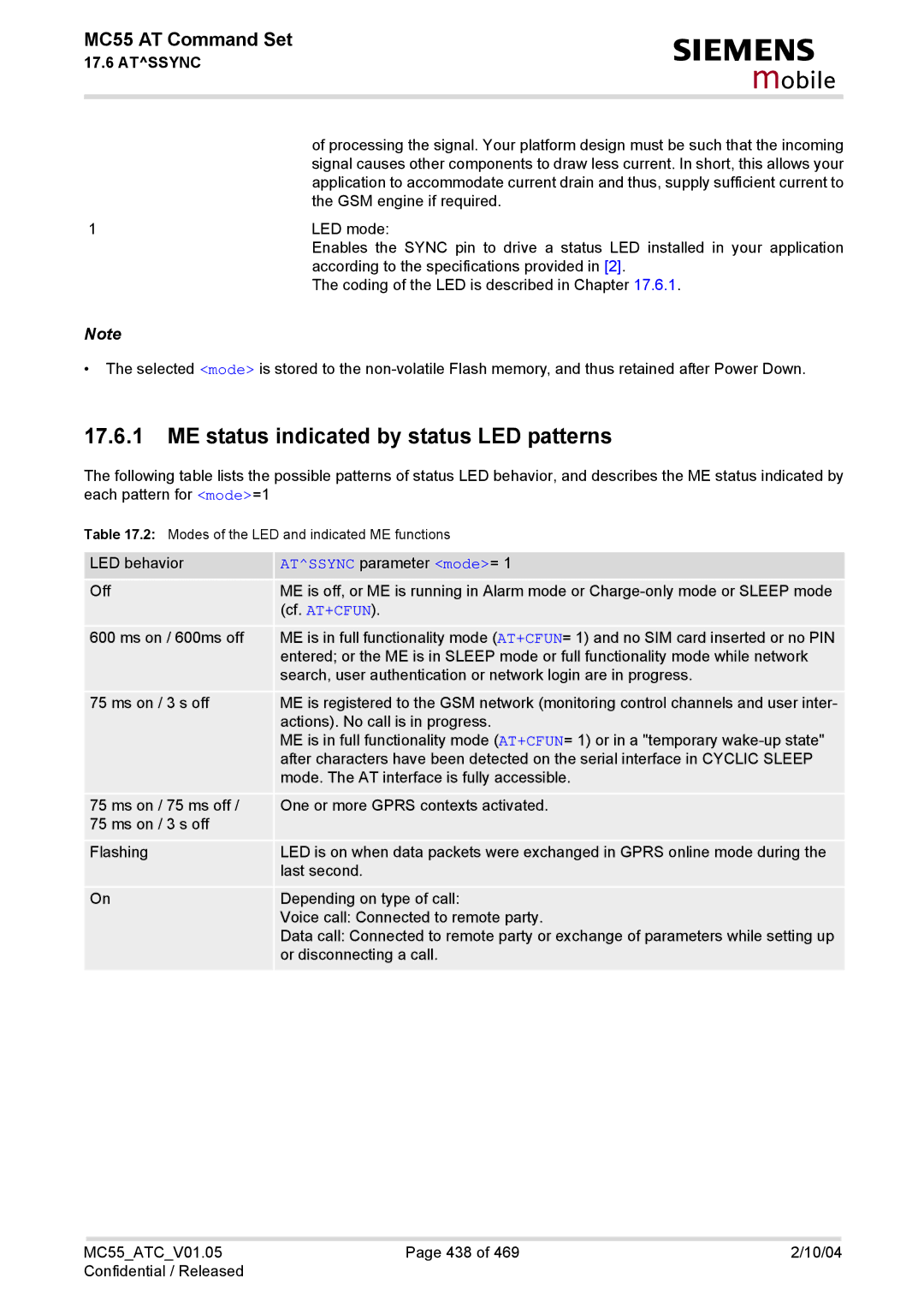
ME status indicated by status LED patterns
Atssync parameter mode=
Miscellaneous Commands
18.1 A/ Repeat previous command line
18.2 ATS3 Write command line termination character
ATS3?
ATS3=n
18.3 ATS4 Set response formatting character
ATS4?
ATS4=n
18.4 ATS5 Write command line editing character
ATS5?
ATS5=n
Restricted access to SIM data after SIM PIN authentication
Appendix
ATDmemn
List of *# Codes
Imei OK
See AT+CLIR
Like +CCWA *see AT+CCWA
FAX SMS SMS+FAX
PAD
Mobile
Available AT Commands and Dependency on SIM PIN
ATDmemn ATDn ATDstr
ATS7 ATS8 ATS10 ATP ATO
ATD*99# ATD*98#
Short Message Service SMS Commands
AT+CRSM Atscks Atscid AT+CXXCID
AT+CALA AT+CCLK Atsbc Atsbv Atsctm Atssync
AT Command Settings storable with AT&W
Mode, mt, bm, ds, bfr
Show
ATS0 Atslcc AT+CR
Factory Default Settings Restorable with AT&F
=0, m=0
Format=0
View=0
Mode=0, mt=0, bm=0, ds=0, bfr=1
ATS3
Summary of Unsolicited Result Codes URC
Sca, tosca, lengthCRLFdata
Smgo mode
+CMT oa, scts, tooa, fo, pid, dcs
Sstn
Alphabetical List of AT Commands
AT+CMGC
AT+FBADLIN
23,
Atssta
ATD*99#
ATT