Studio 500P
United States Government Rights
12G9609
Table of contents
Symptom tables
Messages and error codes
Service checks
Diagnostic aids
Accessing service menus Diagnostics mode
Configuration menu Config Menu
Additional useful menu locations
Handling ESD-sensitive parts -1 Adjustment procedures
Removal procedures
Connector locations and connections
Connections
Assembly 39 Kiosk-vertical and horizontal paper adapters
Page
Laser notices
Laser
Avis relatif à l’utilisation de laser
Avvertenze sui prodotti laser
Avisos sobre el láser
Declaração sobre Laser
Laserinformatie
Lasermeddelelse
Laser-notis
Laser-melding
Japanese Laser Notice
Korean Laser Notice
Safety information
Consignes de sécurité
Sicherheitshinweise
Pautas de Seguridad
Informações de Segurança
Informació de Seguretat
Preface
Definitions
Eneral information
Onfigured model
Data streams
Specifications
Resolution
Print speed and performance print speed
Memory configuration
Dimensions
Description Height Width Depth Weight Printer Studio 500P
Opti ons Duplex 500 page option 15.6 23.4 11 lb
Low voltage model
Power requirements
Electrical specifications
High voltage model
Environment
Acoustics
Media s pecifications
Xecutive Folio1 Tatement1 Universal2 ¾ E nvelope Nvelope
Page
Grain long 20 to 36 lb bond
Selecting print media
Paper characteristics
Weight
Paper
Labels
Storing print media
Card stock
Tools required
Avoiding jams
Print area
Acronyms
Service errors 9xx.xx’s
Diagnostic information Start
Symptom tables
User status and attendance messages
Stop
Understanding the printer operator panel
Menu
Navigation buttons
Understanding the menus
Power-On Self Test Post sequence
128MB 449MH
Symptom tables
Base printer symptoms
High-capacity feeder 2000-sheet symptoms
Envelope feeder symptoms
Paper tray symptoms
Duplex option symptoms
Go to Input trays service check on
Diagnostic information
Messages and error codes
Service error codes
Go to 920.xx-Cold fuser
Desired temperature Noisy thermistor signal
During steady state Fuser not receiving AC power
Service error codes
Chickens for slope Noisy thermistor signal
Service error codes
Go to 922.xx-Cold fuser
922 Hot roll reached final Low wattage or incorrect lamp
922 Hot roll did not reach Low wattage or incorrect lamp
922 Hot roll took too long to Low wattage or incorrect lamp
922 Hot roll timed out Low wattage or incorrect lamp
To reach desired Excessive load on the fuser
Go to 923.xx-Hot fuser
Go to 924.xx-Hot fuser
Go to 925.xx-Hot fuser
Go to Main fan on
Go to Cartridge fan service
Go to Toner sensor service
Go to Printhead service
Go to Main drive service
Board. See System board
Go toMain drive service
See Low voltage power
Inner shield removal on
2-77. or go to
Go to 950.00 through
Eprom mismatch failure on
Through 950.60 Eprom
Upper front cover removal
On page 4-11 or Upper front
Cover removal on
Assembly removal on
See Interconnect card
Following system board, duplex
Error Sub Display text Description/action Code
User status displays
Error Sub Primary message Description/action Code
User attendance messages
May be a poor connection or a hardware failure
Go to StapleSmart finisher service check on
StapleSmart finisher service check on
Check on page 2-113 or Input trays service check on
Following occurs
Or reconnect it
Button assembly service check on
Actions may be taken
Reset Standard USB Port
Jobs may not be restored
Formatted Scheduled Maintenance
Go to Scheduled maintenance on
User message Explanation
User line 2 link messages
Check device connection messages
User status message Explanation
Go to Input sensor service
Error Sub Description Possible causes Action Code Codes
Input sensor service
Sensor Test input tray on
Cable service check on
Drive service check on
Go to Cover closed switch
Go to Fuser exit sensor
To Fuser exit sensor
See Fuser assembly
Sensor service check on
Removal on
Not be functioning correctly
Functioning properly. Go to
499,999 Diagnostic information
Preserve data
Assembly removal on
Assembly removal on
Turn media over to reduce
Between 0 and 99,999 202 Is covering exit
Assembly removal on
Between 100,000 199,999 202 Is covering exit
Assembly removal on
Bounced. Fuser
Assembly removal on
Assembly removal on
Assembly removal on
Count between 400,000 499,999 202 Is covering the exit
Assembly removal on
Assembly removal on
Assembly removal on
Count is not available 202 Is covering the exit
Jam displays on
Operator panel on
Jam displayed on
Pass. See Duplex Feed
Duplex Feed 2 on
Continue selected
Error Sub Description Possible causes Action Code Codes
Roll assembly removal on
Tray autocompensator pick
Service checks
Bin mailbox service check
Problems with excessive static electricity buildup
Xx Paper Jam-Check Bin 1 displays
Bin x is Full-message that bin x is full does not display
Xx Service Error displays
Ready-Binx Full displays and paper feeds into bin
Xx Error code service check
Xx Fan service check
Cartridge fan service check
Main fan
Through 950.29 Eprom mismatch failure
Panel board. See Operator panel board removal on
Through 950.60 Eprom mismatch failure
Model Board bar code Corresponds to P/N…
Charge roll service check
See System board and inner shield removal on
Switch status
Cover closed switch/cable service check
Dead machine service check
Pin number Cover open Cover closed
Voltage on CN2-1 on the LVPS. The voltage should measure
Duplex option service check
Duplex paper jams
23x.xx jam code Jam location
Xx Jam displays on the operator panel
Xx Jam displayed on operator panel
Envelope feeder service check
Error codes on
Xx Service Error, envelopes fail to feed from the hopper
Xx Paper Jam displays, envelope stops in feeder paper path
Redrive assembly removal on
Fuser service checks
Xx-Cold fuser service check
Connector locations at Low voltage power supply on
Fuser assembly. See Fuser assembly removal on
Lvps assembly. See Low voltage power supply removal on
System board assembly. See System board and inner shield
LVPS. See Low voltage power supply removal on
Connector locations at Low voltage power supply removal on
Cover assembly.Fuser narrow media sensor removal on
Xx-Cold fuser check
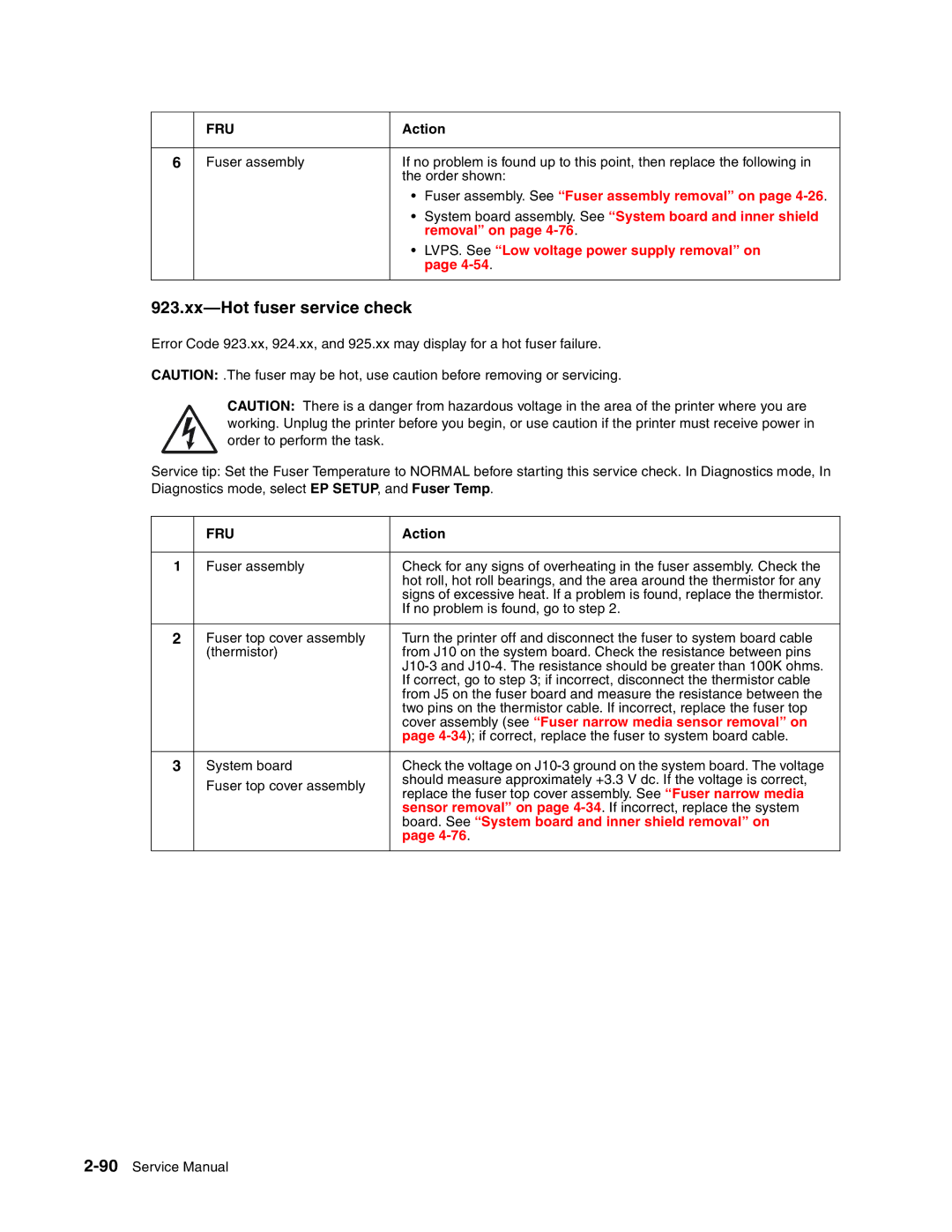
Xx-Hot fuser service check
Cover assembly see Fuser narrow media sensor removal on
Board. See System board and inner shield removal on
Fuser assembly removal on page 4-26. If incorrect, replace
Fuser exit sensor service check
Fuser exit and fuser narrow media sensor status chart
Sensor removal on
Fuser narrow media sensor service check
Fuser exit and fuser narrow media sensor status check
Fuser narrow media sensor removal on
Fuser solenoid service check
Assembly. See Fuser assembly removal on
High-capacity feeder input tray service check
Capacity feeder option control board
Paper out sensor flag
Elevator moves in one direction only
Paper size switch not selecting paper size that is selected
Pin Color Paper size
High-capacity output stacker service check
Excessive noise or vibration
High-capacity output stacker option
Xx Paper Jam Check Bin x, Post incomplete
Input sensor service check
Input trays service check
Optional 250-sheet and 500-sheet trays
Tray x Empty displays when tray x has paper in the tray
Printer does not recognize Tray x is installed
Interconnect card service check
Paper from Tray x does not reach the pass thru sensor
Main drive service check
Xx Paper Jam user
Operator panel service check
One or more operator panel buttons fail
No buttons work
Operator panel display
Error Code 977.xx Network Card
Options service check
Error Code 976.xx Network Card x x=Network card 1, 2, or
Flash Memory Options
Output bin sensor standard tray service check
Standard Bin message
Output expander service check
Service Bin
Xx Paper Jam-Check Bin x, Post incomplete
Paper feed service check
Failures occur mainly near the bottom of the stack of paper
Double feeding paper
Paper size sensing service check
Paper fails to feed from the multipurpose tray
Paper activate springs and ITC switches
Printer does not recognize the paper size selected
Print quality-all black
Parallel port service check
Print quality service check
Run the Parallel Wrap tests on
Print quality-blank
Print quality-random marks
Print quality-blurred or fuzzy print
Print quality-background
Print quality-banding
Print quality-black bands on outer edges
Print quality-residual image
Print quality-light print
Print quality-toner on backside of printed
Printhead service check
Signature button assembly service check
Service error code Explanation
Diagnostic information
Page
Diagnostic information
System board service check
Toner sensor service check
Transfer roll service check
Quality-background on
See Diagnostics mode on page 3-2 for more
Diagnostic aids
Accessing service menus
See Configuration menu Config Menu on
Diagnostics mode
Entering Diagnostics mode
Available tests
See Engine Setting 1 through 4 on
See Disk Test/Clean on
See Defaults on
See Configuration ID on
Exiting Diagnostics mode
Quick Test
Variable Description Value Direction of change
Input source tests
Print quality pages Prt Quality Pgs
Select Single or Continuous
Panel Test
Button Test
Dram Test
Cache Test
Parallel Wrap tests
Serial Wrap tests
Quick Test duplex
Top Margin duplex
Sensor Test duplex
Motor Test duplex
Duplex Motor AA BB CC DD EE FF
Duplex Feed
Feed Tests input tray
Sensor Test input tray
Feed Tests output bins
Feed To All Bins
Order sheets Output bins Are fed
Sensor Test standard output bin
Sensor Test Output Expander
Sensor Test high capacity output stacker
Sensor Tests 5-bin mailbox
Diverter Test
Diagnostic aids
Base Sensor Test
Quick Disk Test
Disk Test/Clean
Flash Test
Count
Defaults
Engine Setting 1 through Model Name
Perm Page Count permanent page count
Configuration ID
Parallel strobe adjustment Par x Strobe Adj
Edge to Edge
Gap Adjust
EP Defaults
Fuser Temperature Fuser Temp
Fuser Page Count
Display Log
Print Log
Exit Diagnostics
Clear Log
Maintenance page count Maint Cnt Value
Configuration menu Config Menu
Entering Configuration Menu
Available menus
Maintenance page counter reset Reset Maint Cnt
Print quality pages Prt Quality Pgs
Ppds Emulation
Download Emuls Demo Mode
Panel Menus
Paper source Size sensing
Paper Prompts
Factory Defaults
Energy Conserve
Env Prompts
Additional useful menu locations
Menu settings
Printing menu settings
Theory
Autocompensator operation
Autoconnect cabling and connectors
Duplex Option
Option microcode
Paper Jam 200/201
Paper Jam Check MP Feeder
Paper Jam Check Env Feeder
23x and 24x jams
201 Paper Jam Remove Cartridge
Page
Paper Jam Open Rear Door
23x Paper Jam Open Duplex Rear Door
Diagnostic aids
Repair information Handling ESD-sensitive parts
Gap adjustment
Adjustment procedures
Fuser solenoid adjustment
Printhead assembly adjustment
Paper alignment assembly adjustment
Step a
Step B
Removal procedures
Fuser wiper cover assembly removal
Covers removals
Redrive cap cover removal
Paper support removal
Left door removal
Redrive door
Right cover removal
Remove the redrive cap. SeeRedrive cap cover removal on
Page
Page
Upper front cover removal
Installation notes
Upper front cover latch removal
Upper front cover outer bezel removal
Multipurpose feeder/lower front cover assembly removal
Left cover handle holder removal
Right cover handle holder removal
Left and right frame extensions
Remove the redrive assembly. See Redrive assembly removal on
Pass thru plate
Laser cover removal
Page
Bevel gear removal
Installation
Cartridge duct removal
Developer drive assembly removal
Developer drive coupler kit removal
ESD cover removal
Fuser assembly removal
Installation notes
Remove the fuser. See Fuser assembly removal on
Fuser exit sensor removal
Installation
Spring replacement
Fuser exit sensor flag and spring removal
Page
Remove the fuser assembly. See Fuser assembly removal on
Fuser lamp removal
Fuser Lamp 220
Description Fuser Lamp 115
40X0122
40X0123
Fuser narrow media sensor removal
Replacement
Fuser narrow media flag and spring removal
Page
Fuser to Lvps AC cable removal
Installation
Page
Fuser top cover removal
Page
Fuser transfer plate removal
Gear release link removal
High voltage power supply removal
Page
Inner paper deflector assembly removal
Input sensor removal
Integrated tray autocompensator assembly removal
Page
Integrated tray autocompensator pick roll assembly removal
Installation
Interconnect card assembly removal
Low voltage power supply removal
Page
Main fan removal
Main drive assembly removal
Page
Page
MPF arm assembly removal
Installation note
MPF lower paper deflector
MPF solenoid assembly removal
MPF pick tire removal
Page
Page
Installation note
Operator panel board removal
Operator panel buttons removal
Outer shield removal
Remove the left door. See Left door removal on
Paper alignment assembly removal
Page
Paper bin full sensor flag removal
Paper size sensing board removal
Power takeoff shaft and spring removal
Printhead removal
Remove the laser cover. See Laser cover removal on
Redrive assembly removal
Signature button contact assembly removal
System board and inner shield removal
Transfer roll assembly removal
Toner sensor removal
Upper front cover hinge assembly removal
BAB
Upper paper deflector assembly removal
USB board assembly removal
4061-xx0
Connector locations and connections Connections
System board
Connector Pin no Signal
System board see System board on
Narmedia
Bldchall
PSIZE2
Connector Pin no Signal static
Autoconnect
Fuser Board not a FRU Connectors
Fuser Board
High-capacity output stacker board
High-capacity Pin
Stacker board
CN no Signal
High voltage power supply
Connector
Interconnect card
Low voltage power supply
Connector CN pin Signal
Output expander control board
Page
Connector locations and connections
Page
Lubrication specifications
Preventive maintenance
Safety inspection guide
Scheduled maintenance
Page
Parts catalog How to use this parts catalog
Model name Configuration Machine type
Assembly 1 Covers
Assembly 1 Covers
Assembly 2 Frame
Assembly 2 Frame
Assembly 3 Frame
Assembly 3 Frame
Assembly 4 Frame
Assembly 4 Frame
Assembly 5 Printhead
Assembly 5 Printhead
Assembly 6 Paper feed-autocompensator
Assembly 6 Paper feed-autocompensator
Assembly 7 Paper feed-multipurpose feeder
Assembly 7 Paper feed-multipurpose feeder
Assembly 8 Paper feed-alignment
Assembly 8 Paper feed-alignment
7-19 has been removed from This document intentionally
Assembly 10 Integrated 500-sheet paper tray
10-1
Assembly 11 Drives-Main drive and developer drive
11-1
Assembly 12 Hot roll fuser
12-1
Assembly 13 Transfer/charging
13-1
Assembly 14 Electronics-power supplies
14-1
Page
Assembly 15 Electronics-card assemblies
Assembly 16 Electronics-shields
16-1
Assembly 17 Cabling diagrams
Assembly 18 Cabling diagrams
Assembly 19 Cabling diagrams
19-1
Assembly 20 Cabling diagrams
20-1
Assembly 21 Cabling diagrams
Frame assembly with solenoid and cable
42S ervice Manual
Assembly 24 Optional 500-sheet paper drawer
Assembly 25 Optional 500-sheet paper tray
Assembly 26 Duplex option
20G0888 Duplex assembly-500-sheet
Assembly 27 Envelope feeder
48S ervice Manual
Assembly 35 High-capacity feeder
Assembly 35 High capacity feeder
Assembly 36 High-capacity feeder
36-1
Assembly 37 High-capacity feeder
Assembly 38 High-capacity feeder
64S ervice Manual
Index
Numerics
Hardware Tests
Fuser narrow media sensor flag and spring
Buttons 2-106,4-67,7-3 description
Page
Page
Page
Page
Part number index
Laser printhead cable assembly
Redrive door assembly 250 sheet 000/010
Laser cable assembly
Printhead assembly includes all cables
Part number index
Page
Part number index
Page
Part number index
Page
500P 4061 Wiring diagram