Connect the MCI Cable to the A25B Cable
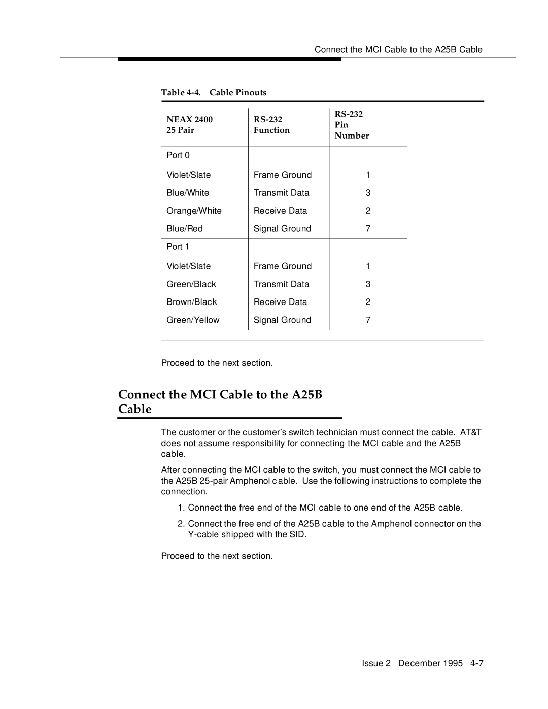
Table 4-4. Cable Pinouts
NEAX 2400 |
| |||
Pin | ||||
25 Pair | Function | |||
Number | ||||
|
| |||
|
|
|
| |
Port 0 |
|
|
| |
Violet/Slate | Frame Ground | 1 |
| |
Blue/White | Transmit Data | 3 |
| |
Orange/White | Receive Data | 2 |
| |
Blue/Red | Signal Ground | 7 |
| |
|
|
|
| |
Port 1 |
|
|
| |
Violet/Slate | Frame Ground | 1 |
| |
Green/Black | Transmit Data | 3 |
| |
Brown/Black | Receive Data | 2 |
| |
Green/Yellow | Signal Ground | 7 |
| |
|
|
|
| |
|
|
|
| |
Proceed to the next section.
Connect the MCI Cable to the A25B
Cable
The customer or the customer’s switch technician must connect the cable. AT&T does not assume responsibility for connecting the MCI cable and the A25B cable.
After connecting the MCI cable to the switch, you must connect the MCI cable to the A25B
1.Connect the free end of the MCI cable to one end of the A25B cable.
2.Connect the free end of the A25B cable to the Amphenol connector on the
Proceed to the next section.
Issue 2 December 1995
