NEAX 2400 Switch Administration
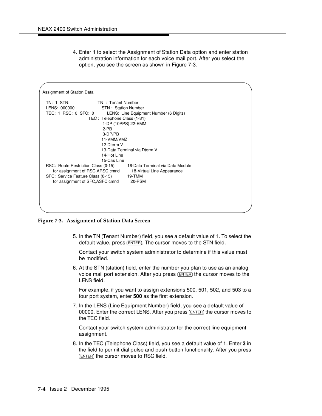
4.Enter 1 to select the Assignment of Station Data option and enter station administration information for each voice mail port. After you select the option, you see the screen as shown in Figure
Assignment | of Station Data |
|
| |
TN: | 1 | STN: | TN : | Tenant Number |
LENS: |
| 000000 | STN : | Station Number |
TEC: | 1 | RSC: 0 SFC: 0 | LENS: | Line Equipment Number (6 Digits) |
|
|
| TEC : | Telephone Class |
|
|
|
| |
|
|
|
| |
|
|
|
| |
|
|
|
| |
|
|
|
| |
|
|
|
| |
|
|
|
| |
|
|
|
| |
RSC: | Route Restriction Class |
| ||
| for assignment of RSC,ARSC cmnd | |||
SFC: | Service Feature Class |
| ||
| for assignment of SFC,ASFC cmnd | |||
|
|
|
|
|
Figure 7-3. Assignment of Station Data Screen
5.In the TN (Tenant Number) field, you see a default value of 1. To select the default value, press ENTER . The cursor moves to the STN field.
Contact your switch system administrator to determine if this value must be modified.
6.At the STN (station) field, enter the number you plan to use as an analog voice mail port extension. After you press ENTER the cursor moves to the LENS field.
For example, if you want to assign extensions 500, 501, 502, and 503 to a four port system, enter 500 as the first extension.
7.In the LENS (Line Equipment Number) field, you see a default value of 00000. Enter the correct LENS. After you press ENTER the cursor moves to the TEC field.
Contact your switch system administrator for the correct line equipment assignment.
8.In the TEC (Telephone Class) field, you see a default value of 1. Enter 3 in the field to permit dial pulse and push button functionality. After you press ENTER the cursor moves to RSC field.