Configuring DS3-ATM Cards

14


Introduction DS3-ATM . . . . . . . . . . . . . . . . . . . . . . . . . . . . . . . . . . . . . . . . . . . . . . . .14-1

Overview of DS3-ATM settings . . . . . . . . . . . . . . . . . . . . . . . . . . . . . . . . . . . . . . . . . 14-1

Examples of DS3-ATM configurations . . . . . . . . . . . . . . . . . . . . . . . . . . . . . . . . . . . . 14-3

Introduction DS3-ATM

The DS3-ATM cards (DS3-ATM and DS3-ATM2) support one 44.736Mbps interface for connecting to one ATM switch. At a minimum, you must enable the line and specify a nailed group. TAOS units use the nailed group to direct traffic to the interface.

Note: The DS3-ATM card is supported on the MAX TNT and DSLTNT platforms only. The DS3-ATM2 card is supported on the APX 8000, MAX TNT, and DSLTNT platforms. Both cards use the same configuration profiles, but at the time of this writing, the DS3-ATM2 card does not support ATM-Frame Relay circuit configurations. Maximum performance with the DS3-ATM2 card is achieved using RFC 1483 ATM-AAL5-CPCS-PDU encapsulation.

This chapter refers to both the
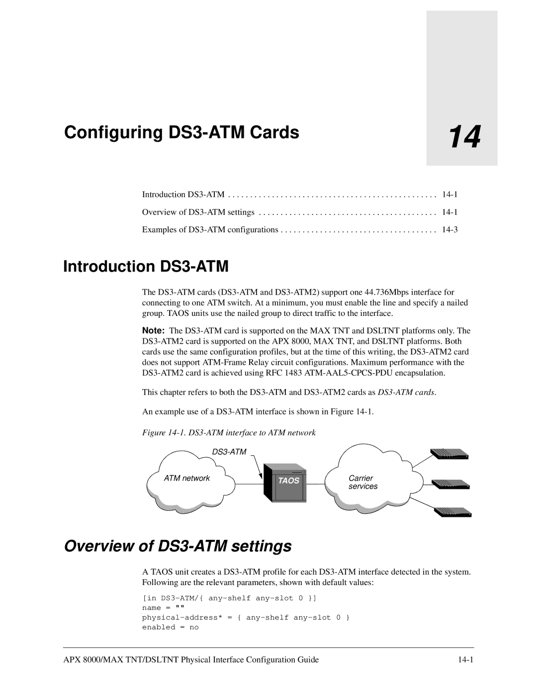
 DS3-ATM and DS3-ATM2 cards as DS3-ATM cards.

An example use of a DS3-ATM interface is shown in Figure 14-1.

Figure 14-1. DS3-ATM interface to ATM network

DS3-ATM

ATM network

TAOS

Carrier services

Overview of DS3-ATM settings

A TAOS unit creates a DS3-ATM profile for each DS3-ATM interface detected in the system. Following are the relevant parameters, shown with default values:

[in DS3-ATM/{ any-shelf any-slot 0 }] name = ""

physical-address* = { any-shelf any-slot 0 } enabled = no

APX 8000/MAX TNT/DSLTNT Physical Interface Configuration Guide

14-1

Page 141
Image 141
Lucent Technologies 7820-0802-003 manual Configuring DS3-ATM Cards, Overview of DS3-ATM settings