J2-Super Series
Safety Instructions
To prevent electric shock, note the following
HC-SFS202
HC-SFS81
HC-UFS
HC-SFS121
COM
Wiring
RA EMG 24VDC
Usage
Dispose of the product as general industrial waste
Maintenance, inspection and parts replacement
Machine directive
Configuration
EMC directive
Low voltage directive
Wiring
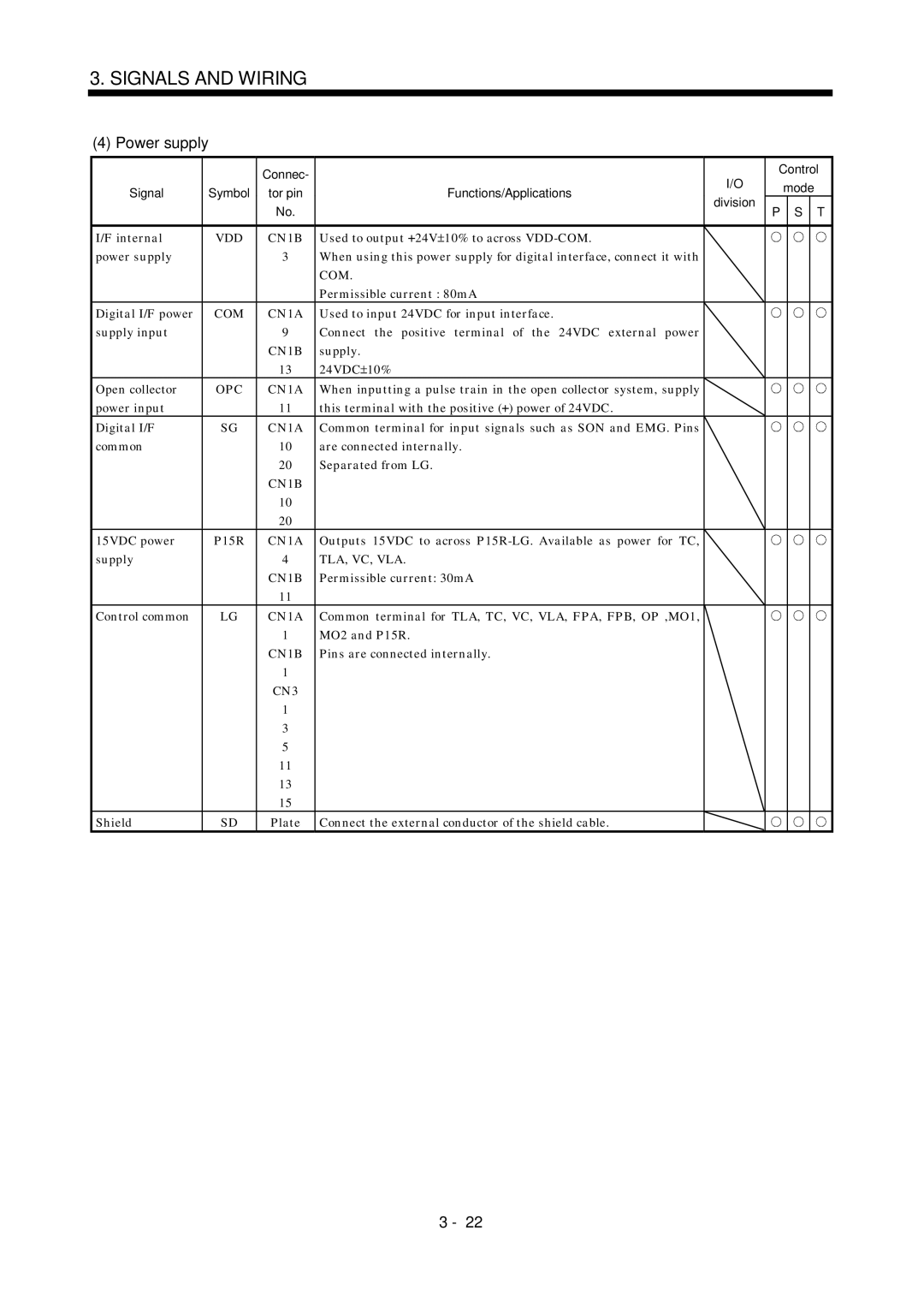
Power supply
Grounding
Performing EMC tests
Auxiliary equipment and options
Use UL/C-UL standard-compliant products
MR-J2S-10A1 20A1 MR-J2S-40A1 60A MR-J2S-70A to 350A
Contents Functions and Configuration
To 5
To 4
11- 1 to 11
To 9
10- 1 to
10-12
13-13
12.3
12.4
13.1
14-27
14-24
14-25
14-26
Page
Introduction
Position control mode
Speed control mode
Torque control mode
Function block diagram of this servo is shown below
Function block diagram
Servo amplifier standard specifications
Section
Function list
Parameter No
Parameters
Input signal selection
Model code definition Rating plate
Different types
Combination with servo motor
Model
Output analog monitor data Name plate Charge lamp
Battery holder
Parameter setting operations
Parts identification MR-J2S-100A or less
MR-J2S-200A or more
Backup Display 5-digit, seven-segment LED shows the servo
Functions and Configuration
Magnetic contactor
For 3-phase 200V to 230VAC or 1-phase 230VAC
MRZJW3-SETUP121E
Regenerative brake option Section
Magnetic contactor Section Cables
For 1-phase 100V to 120VAC
Servo configuration software Section
No-fuse breaker Section Regenerative brake option
No-fuse breaker 2 Regenerative brake option
SETUP121E
MRZJW3
Installation
Control box
Others
Installation of two or more servo amplifiers
Keep out foreign materials
Cable stress
Signals and Wiring
Standard connection example
Position control mode FX-10GM
Signals and Wiring
CN1B
AD75P A1SD75P
Signals and Wiring
CN1B VDD COM CN1A SP1
Signals and Wiring
CN1B VDD COM CN1A
Signals and Wiring
Internal connection diagram of servo amplifier
CN1B CN3 RXD TXD MO1 MO2 RDP RDN
I/O signals Connectors and signal arrangements
Signal arrangement
CN1A CN2 MDR MRR BAT
For note, refer to the next
CN1A and CN1B signal assignment
OPC
Symbols and signal names
Reverse rotation
Signal explanations
Input signals
Servo-on
ST2 CN1B
CN1B
TL1
ST1 CN1B
SP3
Speed selection
SP1
SP2 CN1B
CDP
CN1A
CM1
CM2
TLA CN1B
LOP CN1B
TLC
Output signals
ALM CN1B
INP CN1A
AL.8E
AL.8A
AL.1A
Refer to for the communication function
Communication
TLA, VC, VLA
24VDC
Negative logic Positive logic
VDD OPC
Differential line driver system Connect as shown below
OFF
Electronic gear switching
In-position INP
Ready RD
Parameter No TLA
Torque limit
TLA
Parameter No Parameter No
Generally, make connection as shown below
Speed control mode Speed setting
No servo lock
As in .4.1
Speed reached SA
RS2
RS1 RS2
Speed limit
CCW
Setting of parameter Speed limit value No to
Control change LOP
Position/speed control change mode
Torque limit in position control mode
Position control mode Speed control mode
Speed setting in speed control mode
As in .4.2
Speed/torque control change mode
Torque limit in speed control mode
Speed control mode Torque control mode
As in .4.3
Speed limit in torque control mode
Torque control in torque control mode
Torque limit in torque control mode
Torque control mode Position control mode
Torque/position control change mode
0V on OFF
RES OFF
Precautions for alarm occurrence
SON OFF
ALM OFF
OPC PG NG PP NP
Interfaces 3.6.1 Common line
CN1A DC24V CN1B VDD COM
TLA
Digital input interface DI-1
Detailed description of the interfaces
Digital output interface DO-1
COM 24VDC VDD VDD-COM
Lamp load
Pulse train input interface DI-2
Conditions of the input pulse
Encoder pulse output DO-2
Differential line driver system 1 Interface
Open collector system Interface
Analog output Output 10V Max.1mA
Output pulse
Analog input
Input impedance 10 to 12k
SON
Source input interface
Nfbmc
VAC
EMG SON VDD COM ALM
Terminals
VDD COM EMG
Power-on sequence Power-on procedure
Timing chart
Emergency stop
Connection diagram
HC-SFS121 B to 301 B
HC-KFS053 B to 43 B
HC-MFS053 B to 73 B
HC-UFS13 B to 73 B
Black
3 I/O terminals HC-KFS HC-MFS HC-UFS3000r/min series
White
BAT
HC-SFS HC-RFS HC-UFS2000 r/min series
Earth
MDR CNT MRR
COM MBR 24VDC
Setting
Emergency stop signal EMG ON/OFF
Timing charts
Both main and control circuit power supplies off
Alarm occurrence
CN1A CN1B
Approx mm
Connection
Instructions for the 3M connector
Memo
Before starting operation, check the following
When switching power on for the first time
Machine
Test operation
Selection of control mode
Position control mode Power on
Parameter setting
Make home position return as required
Command pulse input
Servo-on
Home position return
Start
Speed control mode Power on
Torque control mode Power on
Multidrop communication
Parameters
Item list
Lists
MO2
FFC
TLO
MO1
LPF
SIC
NH1
NH2
STY ParametersBasic 1 *OP1
Details list
Point
CMX CDV
Auto tuning 0105
Used to set speed 1 of internal speed limits
PG1
In-position range 100
Operation
STC
STB
BPS
14 TQC ParametersBasic
TQC
Droop pulses
MOD Analog monitor output 0100
8V/max. torque Motor speed 8V/max. speed
Generated torque 8V/max. torque
Status display selection 0000
Used to select the status display shown at power-on 001Fh
000A
19 *BLK Basic parameters 20 *OP2 Expansion parameters
Parameter block 0000
Initial
444 888 777 555
Function selection 3 Command pulse selection 0000
21 *OP3 22 *OP4 Expansion parameters
Function selection 0000
Analog torque limit internal torque limit
Feed forward gain Used to set the fee forward gain
Will be almost zero Zero speed
Internal torque limit 1 Parameter No
PG2
Analog speed command offset
29 VCO
MBR
980 1000 0000
Clear signal
Used to set the differential compensation
CN1B-5 CN1B-14 CN1A-8 CN1B-7 CN1B-8 CN1B-9
SP2 ST1 RS2 ST2 RS1 SP3 CM1 CM2 TL1 CDP
Signal selection 2 parameter No
DI2
0111
48 *DI7
DI4
DI5
DI6
Not output CN1A-19 CN1B-18 CN1A-18 CN1B-19 CN1B-6
49 *DO1 Expansion parameters
Used to select the protocol of serial communication
51 *OP6 53 *OP8 Parameters 54 *OP9 Expansion
Expansion parameters 59 NH2
55 *OPA
Function selection a 0000
Vicb
60 LPF Expansion parameters 61 GD2B 62 PG2B 63 VG2B
Low-pass filter/adaptive vibration suppression control 0000
CMX4
CMX3
SC5
Parameter No.4
Detailed description 5.2.1 Electronic gear
Concept of electronic gear
Parameter No.3
65536 32768
131072 65536
1125
Instructions for reduction
131072 2000/60 Pulse/s
Setting for use of AD75P
131072 3000/60 Pulse/s
3000 131072 4096
3000 131072
AD75P
Analog output
Change the following digits of parameter No.17
Alarm history clear
For step input
Position smoothing
For trapezoidal input
Memo
Display and Operation
Display flowchart
Display examples
Status display
Following table lists display examples
CMX/CDV
Status display list
Changing the status display screen
Control mode Status display at power-on
Diagnostic mode
Display and Operation
Alarm mode
Operation example
Parameter mode
Expansion parameters
CN1A CN1B CN1B CN1B CN1B CN1A
External I/O signal display
Display definition
CN1B CN1B CN1A CN1B
Symbol and signal names
Control modes and I/O signals
Default signal indications
Output signal forced output do forced output
Mode change
Jog operation
How to use the buttons is explained below
Termination of jog operation
Positioning operation
How to use the keys is explained below
Travel distance pulse 10000 Speed r/min 200
Motor-less operation
To terminate the motor-less operation, switch power off
Termination of motor-less operation
Gain adjustment mode explanation
General Gain Adjustment
Time
Adjustment sequence and mode usage
Adjustment using servo configuration software
You can automatically set the optimum gains
Position control gain
Auto tuning Auto tuning mode
Speed control gain
PG2,VG2,VIC
Auto tuning mode operation
Block diagram of real-time auto tuning is shown below
PG1,VG1
Basic procedure
Adjustment procedure by auto tuning
Response level setting in auto tuning mode
Adjustment procedure
Manual mode 1 simple manual adjustment
Operation of manual mode
Adjustment by manual mode
Suppression of machine resonance
For position control
General Gain Adjustment
Adjustment description
Interpolation mode
Following parameters are adjustable manually
Adjustment procedure
100Hz 105Hz 130Hz 160Hz 200Hz 240Hz 300Hz
Auto tuning selection
15Hz
30Hz
Memo
Machine resonance suppression filter Function
Special Adjustment Functions
Deep 40dB 14dB 8dB Shallow 4dB
Parameters
Adaptive vibration suppression control Function
Low-pass filter Function
Applications
Gain changing function
Used to set the changing condition values
Position control gain Rad/s
Speed control gain Rad/s
Speed Integral Changing ratio Compensation to VIC
Gain changing time constant CDT parameter No
Parameters No , 34 to
Gain changing selection CDP parameter No
Gain changing condition CDS parameter No
Gain changing operation
This operation will be described by way of setting examples
When you choose changing by external input
Setting
Position control gain 120 Speed control gain 3000 4000
When you choose changing by droop pulses
Speed integral compensation 250 Changing ratio
Gain changing selection 0003
Memo
10,000 to 30,000hours 2 to 3 years
Inspection
Life
100,000 times
Memo
LSP/LSN-SG are not Connected No pulses is input
Position control mode Troubleshooting
Trouble at start-up
Make operation instable
Chapter
CMX CDV
How to find the cause of position shift
Power supply of CN1 cabling is
Torque control mode
Alarms and warning list
When alarm or warning has occurred
Change the servo amplifier
A160V or Control power failure of 60ms or Less Longer
MR-J2S
A183V or
Position erase Data in error
Alarm AL.17 or AL.19 occurs if
CN1B and CN3 connectors are Disconnected
Ground fault Occurred at Output wires are in contact at
Option
Reexamine acceleration
Change lead
Option, change regenerative brake
AL.35 Command Input pulse Pulse frequency of the command
Computer Personal computer faulty
AL.EA ABS
Remedies for warnings
TE1
TE1 TE2
MR-J2S-70A MR-J2S-100A
MR-J2S-70A MR-J2S-100A
MR-J2S-200A MR-J2S-350A
MR-J2S-200A MR-J2S-350A
Threaded type
Connectors Servo amplifier side Sumitomo 3M make
Insulation displacement type
Soldered type
#4-40
DE-C1-J6-S6 34.51.36 190.75 24.990.98 331.30 60.24
Memo
Electronic thermal relay protection characteristics
Overload protection characteristics
MR-J2S-10A to MR-J2S-100A
HC-MFS43 HC-UFS43
HC-KFS053
HC-MFS053 HC-UFS13 HC-KFS23
HC-MFS23 HC-UFS23 HC-KFS43
Heat dissipation area for enclosed servo amplifier
Temperature distribution in enclosure
Mm/minin/min
There is internal relay delay time of about 30ms
12.2
Mmin
HC-RFS series HC-UFS 2000r/min series
HC-MFS series
HC-SFS1000r/min series
HC-SFS2000r/min series HC-SFS3000r/min series
MR-JCCBL M-H MR-JHSCBL M-H MR-ENCBL M-H
Encoder cable flexing life
MR-JCCBL M-L MR-JHSCBL M-L
Selection of the regenerative brake option
Options and Auxiliary Equipment
1047 JM No
JM No 1047
No regeneration
Connection of the regenerative brake option
MR-RB50
Outline drawing
MR-RB032 MR-RB12
MR-RB32 MR-RB30
HC-KFS
Cables and connectors Cable make-up
MR-JHSCBL M-H
MR-JCCBL M-L
MR-JCCBL M-H
MR-JHSCBL M-L
MR-J2HBUS M
MR-J2CN1
MR-J2TBL M
MR-TB20
Standard flexing life Long flexing life
For use of AWG24
MDR
MR-JHSCBL M-L
MRR SHD
MR-JHSCBL2M-L
MR-CPCATCBL3M
Communication cable
TXD RXD GND RTS CTS DSR DTR
For CN1A For CN1B
How to use the junction terminal block
Junction terminal block MR-TB20
Terminal labels
B10 A10
Junction terminal block cable MR-J2TBL M Model MR-J2TBL M
SP2 SP1 ST1
INP ALM
TE1 CN3A CN3B CN3C MO1 MO2 VDD COM EMI MBR
Maintenance junction card MR-J2CN3TM Usage
MR-J2HBUS M
CN3 CN3B CN3A CN3C
Bus cable MR-J2HBUS M
Battery MR-BAT, A6BAT
System configuration
CN3 CN2
Configuration diagram 1 When using RS-232C
5mm2 for use of the HC-RFS203 servo motor
Recommended wires Wires for power supply wiring
Recommended wires
Auxiliary equipment
Recommended crimping terminals
Wires for cables
Wires for option cables
Wire specifications
No-fuse breakers, fuses, magnetic contactors
Power factor improving reactors
Noise reduction techniques
Relays
Following relays should be used with the interfaces
Surge absorbers
Options and Auxiliary Equipment
10 to 100MHZ 100 to 500MHZ 150
Noise reduction products
Ex A.2003
Outline drawing
FR-BLFMR-J2S-350A
NV-SF
Leakage current breaker Selection method
NV-CF
Selection example
MR-J2S-200A MR-J2S-350A SF1253
EMC filter
Combination with the servo amplifier
SF1252
Cable connection diagram
Configuration 14.1.1 RS-422 configuration Outline
Wire as shown below
Single axis of servo amplifier is operated
14.1.2 RS-232C configuration Outline
Description
Communication specifications 14.2.1 Communication overview
LSB MSB
RS-422/RS-232C serial interface selection
Communication delay time
Station number setting
Communication baudrate
Transmission of data from the controller to the servo
Protocol
Data length depends on the command
Recovery of communication status by time-out
Data frames
For example, 61H is transmitted in hexadecimal for group a
JIS8 unit codes are used
SOH
Error codes
Checksum
Checksum range
Retry operation
Time-out operation
STX
Communication procedure example
Initialization
Data item Value Description
00 to
Parameter Command
External I/O signals Command
Alarm history Command
Current alarm Command
Current alarm Command 02
Group setting Command 1F
Write commands Status display Command
Group setting Command 9F
Operation mode selection Command 8B
External input signal disable Command
Data for test operation mode Command 92 A0
Processing the read data
Detailed explanations of commands 14.12.1 Data processing
Writing the processed data
1EA5
Command Data No
Status display Status display data read
Status display data clear
00 to
Parameter Parameter read
Parameter write
Command Data No Set data
00 to See below
External output pin status read
Reply ON/OFF statuses of the input pins are sent back
Enable
Disable/enable of external I/O signals DIO
Signal Status
External input signals DI
External input signal ON/OFF test operation
Enable the disabled external input signals
Test operation mode Instructions for test operation mode
1EA5 Choose the test operation mode
Cancel the test operation mode
Jog operation
Command Data No Setting data
Output signal pin ON/OFF do forced output
Choosing do forced output in test operation mode
External output signal ON/OFF
Erase the alarm history Send command 82 and data No
Alarm history Alarm No. read
For example, 0032 means AL.32 and 00FF means AL. no alarm
Alarm occurrence time read
Read of the status display at alarm occurrence
Current alarm Current alarm read
Current alarm clear
Software version
Other commands Servo motor end pulse unit absolute position
Command unit absolute position
Reply Slave station sends back the requested command pulses
Memo
LSO
Outline 15.1.1 Features
Restrictions
CPU
General-purpose programmable controller
Specifications Specification list
CN1A CN2 CN1B
Battery connector Operation window
Standard connection diagram
Absr
Signal explanation
Absm
Amplifier is in the ABS transfer mode, and the functions
Confirmation of absolute position data transfer
Startup procedure Battery installation
Resetting of absolute position erase alarm AL.25
Home position setting
Absolute position data transfer protocol
Data transfer procedure
SON on
Timing chart
At power-on
Transfer method
CN1A-18 Positioning completion ABS data bit
CN1B-4 Positioning completion ABS data bit
Detailed description of absolute position data transfer
Ffff FFF6
Therefore, the check sum of 10 ABS data is 2Db
Transmission error
Yes AL.E5 warning Signal is not turned OFF
At the time of alarm reset
EMG OFF
At the time of emergency stop reset
Send ABS data
DOG OFF
Home position setting Dog type home position return
Data set type home position return
Use of servo motor with electromagnetic brake
Absolute Position Detection System
ABS
Examples of use MELSEC-A1S A1SD71 Instructions
ABS coordinate system
Slot No 1 2 3 4 5 6
A1SX40
A1SCPU
Y4B
Sequence program example
PLS
PLS
100 10 to
PLS M12 RST C2
Saving ABS 32-bit data Clearing register
Reading 4 bits
A1SD71 reading home position address
ABS transfer retry start pulse
Axis start program
Electromagnetic brake output
Dtop
Sequence program 2-axis control
FX-32MT FX-1PG
Melsec FX2N-32MT FX2N-1PG Connection diagram
FX2N-32MT FX2N-1PG
PII
0PPS
VII
Electromagnetic brake output
M62 Sum check discrepancy greater T200 Retry wait timer M63
Clear signal on timer request
T203 Ready to send response timer
To K0 DTO K0 Dmov K0
ABS data transfer program for X-axis
SET
Zrst RST
PLS ABS
Setting servo-on request Retry control
OFF
From K0
Changing X-axis present position data
ABS transfer Zero speed mode ABS transfer mode
A1SCPU
Melsec A1SD75AD75 Connection diagram
Absolute Position Detection System
Y3A
Output signal reset
Reading A1SD75 1-axis RDY
Masking ABS data sign
WOR ROR PLS
ABS request reset
Dmov A0
Wand
Y1D PC RUN
Servo positioning completion
H0000 K1154 D3
Busy
Differences between A1SD75 AD75 and A1SD71 AD71
Y1D
Absolute Position Detection System
Confirmation of absolute position detection data
ABS Y4B
Y4A
ABS communication error
Error resetting conditions
App
Appendix
PWM
App 2. Analog monitor block diagram Appendix
App 3. Status display block diagram Appendix
Memo
SHNA030006-A
Manual number is given on the bottom left of the back cover
Sep.,2000 SHNA030006-B
Sep.,2000