2CONNECTION OPTIONS
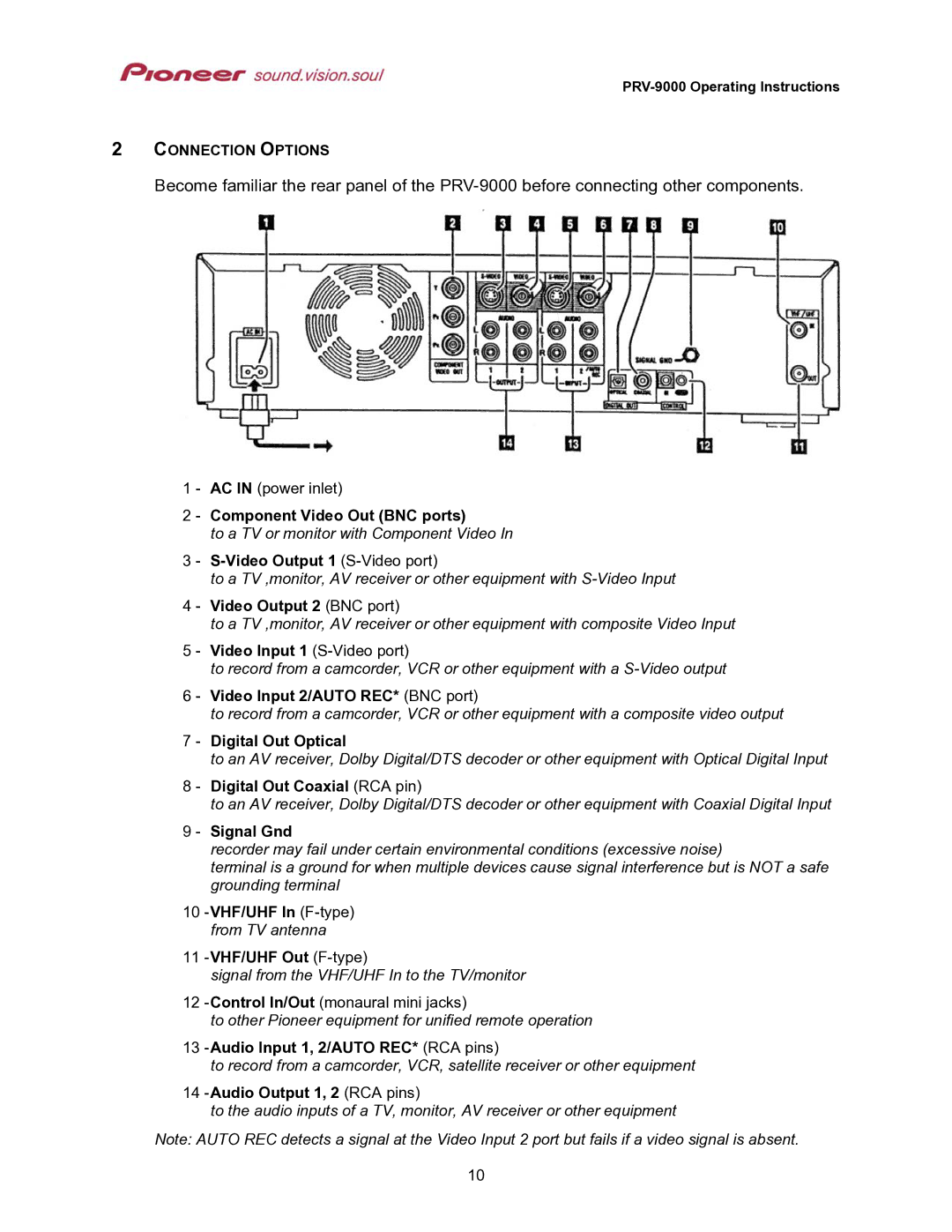
Become familiar the rear panel of the
1 - AC IN (power inlet)
2 - Component Video Out (BNC ports)
to a TV or monitor with Component Video In
3 -
to a TV ,monitor, AV receiver or other equipment with
4 - Video Output 2 (BNC port)
to a TV ,monitor, AV receiver or other equipment with composite Video Input
5 - Video Input 1
to record from a camcorder, VCR or other equipment with a
6 - Video Input 2/AUTO REC* (BNC port)
to record from a camcorder, VCR or other equipment with a composite video output
7 - Digital Out Optical
to an AV receiver, Dolby Digital/DTS decoder or other equipment with Optical Digital Input
8 - Digital Out Coaxial (RCA pin)
to an AV receiver, Dolby Digital/DTS decoder or other equipment with Coaxial Digital Input
9 - Signal Gnd
recorder may fail under certain environmental conditions (excessive noise)
terminal is a ground for when multiple devices cause signal interference but is NOT a safe grounding terminal
10-VHF/UHF In (F-type) from TV antenna
11-VHF/UHF Out (F-type)
signal from the VHF/UHF In to the TV/monitor
12
to other Pioneer equipment for unified remote operation
13
to record from a camcorder, VCR, satellite receiver or other equipment
14 -Audio Output 1, 2 (RCA pins)
to the audio inputs of a TV, monitor, AV receiver or other equipment
Note: AUTO REC detects a signal at the Video Input 2 port but fails if a video signal is absent.
10
